Chaotic pendulum device capable of continuously demonstrating

A technology of chaotic pendulum and parallel arrangement, which is applied in the field of popular science education or teaching, can solve the problems that the chaotic pendulum mechanism cannot continue to operate for a long time, the chaotic phenomenon cannot be continuously observed, and the structure is too simple, so as to increase interactivity and interest. Protects against damage and prolongs the swing time

Active Publication Date: 2016-12-14
HEFEI GENERAL MACHINERY RES INST
View PDF5 Cites 0 Cited by
  • Summary
  • Abstract
  • Description
  • Claims
  • Application Information

AI Technical Summary

Problems solved by technology

[0004] In the teaching process, teachers usually draw chaotic mechanisms on the blackboard to try their best to describe the state of chaotic phenomena. However, due to the invisibility of chaos itself, it is difficult to teach intuitively.
There is an example of a simple chaotic pendulum mechanism in modern educational activities, most of which are two-stage mechanisms. This simplest mechanism has many shortcomings in practical activities. First, because the structure is too simple, it makes visitors or learners misunderstand, thinking that The chaotic pendulum is such a simple mechanism, thus ignoring the different chaotic pendulum mechanism in real life. Second, because the chaotic pendulum mechanism cannot continue to operate for a long time, visitors or learners cannot understand the chaotic phenomenon for a long time. continuous observation and, therefore, cannot be understood phenomenally

Method used


Image

  • Chaotic pendulum device capable of continuously demonstrating
  • Chaotic pendulum device capable of continuously demonstrating
  • Chaotic pendulum device capable of continuously demonstrating

Examples


Embodiment 1

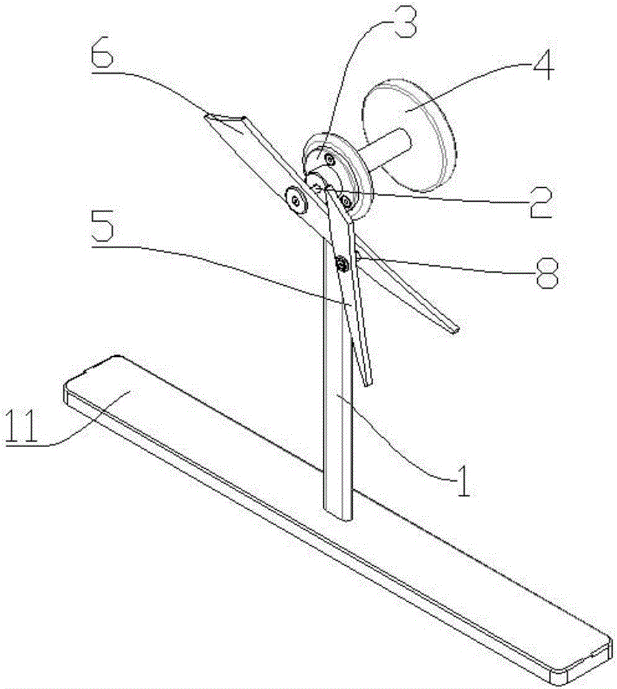
[0030] like figure 1 As shown, the demonstration device includes a bracket 1, a main rotating shaft 2 that rotates around its own axis, and a first rotor blade 6 that is fixed on the main rotating shaft 2 and rotates synchronously with the main rotating shaft 2. The main rotating shaft 2 passes through the bearing seat 3 is installed on the support 1, and the blade surface of the first rotating blade 6 is fixed with an auxiliary rotating shaft 8 which is far away from the main rotating shaft 2 and arranged parallel to the main rotating shaft 2, and is installed on the auxiliary rotating shaft 8 The second rotating vane 5 that can freely rotate around the auxiliary rotating shaft 8; the axis of the main rotating shaft 2 is perpendicular to the blade surface of the first rotating blade 6 and the blade surface of the second rotating blade 5; the main rotating shaft 2, auxiliary The rotating shaft 8 is arranged along the blade length direction of the first rotating blade 6, wherei...

Embodiment 2

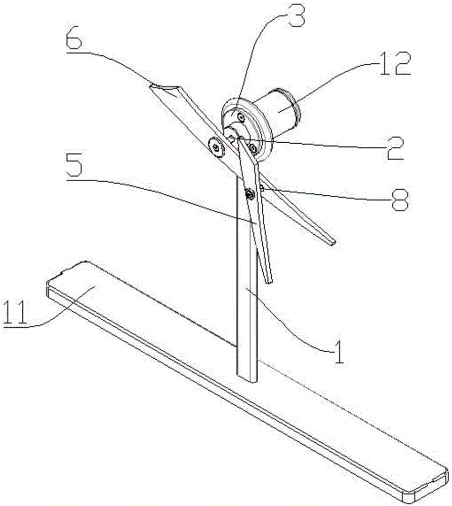
[0033] like figure 2 As shown, the difference from Embodiment 1 is that the end of the main rotating shaft 2 in this chaotic pendulum demonstration device is provided with a motor 12 for driving the main rotating shaft 2 to rotate.

[0034] A detailed description of the working process of the demonstration device: first, the visitor or learner starts the motor 12 momentarily and then cuts off the power, and drives the demonstration device in a clockwise or counterclockwise direction to start demonstration: the first rotary blade 6 starts synchronously with the main rotating shaft 2 Rotate; At this time, the second rotating blade 5 has also started its own free rotation around the auxiliary rotating shaft 8, and the direction and speed of rotation are inconsistent with the first rotating blade 6; in the first rotating blade 6, the second During the rotation process of the rotating vane 5, due to the difference in the initial force received, after a period of rotation, the firs...

Embodiment 3

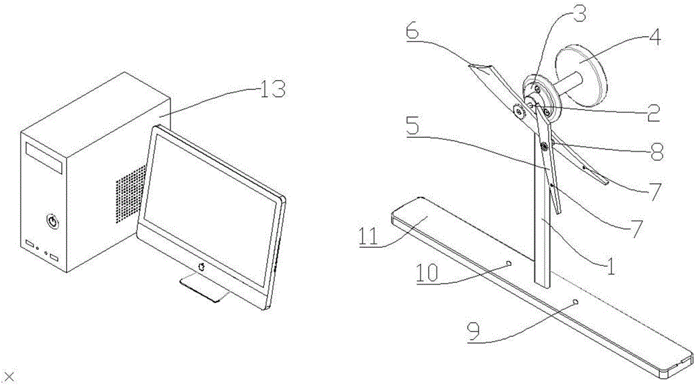
[0036] like image 3 As shown, the difference from Embodiment 1 is that the bracket 1 is fixedly mounted on the base 11, and the base 11 is installed with a position sensor 9 and an electromagnetic driver that drive the first rotary vane 6 and the second rotary vane 5 to continuously swing. 10. This demonstration device also comprises the infrared sensor 7 that is installed on the blade tip of described first rotary vane 6, the second rotary vane 5, is used to capture the camera of described infrared sensor signal, collects the signal that described camera captures and The signal processing generates the computer 13 of the motion trajectory and the display for synchronous real-time display of the motion trajectory. Of course, the infrared sensor 7 can be selectively installed on one of the first rotating vane 6 and the second rotating vane 5 .

[0037] The detailed description of the working process of the demonstration device: first, the visitor or learner turns the rotary ...


PUM


Abstract

The invention relates to a chaotic pendulum device capable of continuously demonstrating. The device comprises a bracket, a main rotating shaft and a first vane, wherein the main rotating shaft can rotate around the axis of the main rotating shaft; the first vane is fixed on the main rotating shaft and can synchronously rotate following the main rotating shaft; the main rotating shaft is arranged on the bracket through a bearing base; an auxiliary rotating shaft which is away from the main rotating shaft and is parallel to the main rotating shaft is fixedly arranged on the first vane surface; a second vane capable of freely rotating around the auxiliary rotating shaft is arranged on the auxiliary rotating shaft; the device further comprises a position sensor and an electromagnetic driver for driving the first vane and the second vane to continuously swing. Through the chaotic pendulum device capable of continuously demonstrating, the visitor or learner can clearly view the chaotic phenomenon shown by the chaotic pendulum. When the demonstrating device is about to stop swinging, the position sensor and the electromagnetic driver are started to drive the first vane and the second vane to continuously swing, so that the visitor or learner can master the knowledge related to the chaotic phenomenon by long-term viewing.

Description

technical field [0001] The invention belongs to the field of popular science education or teaching, and in particular relates to a chaotic pendulum device capable of continuous demonstration. Background technique [0002] The certainty of a dynamical system is a mathematical concept, which means that the state of the system at any moment is determined by the initial state. Although the motion state at any future moment can be calculated according to the initial state data and motion laws of the motion, since the measurement of the initial state data cannot be completely accurate, errors in the predicted results are bound to occur, and even unpredictable. The predictability of motion is a physical concept. It is not contradictory that a movement can be unpredictable even if it is deterministic. The success of Newtonian mechanics, especially its success in predicting Neptune, has to a certain extent caused misunderstandings, equating certainty and predictability, thinking th...

Claims


Application Information

Patent Timeline
IPC IPC(8): G09B23/08
CPCG09B23/08
Inventor 苏本林李小瓯仝文浩吉胜旺方猛张爱群洪先亮冯帅将李春李璇
Owner HEFEI GENERAL MACHINERY RES INST
Why Eureka
Try Eureka