Three-leaf chaotic pendulum demonstration device

A demonstration device, the technology of chaotic pendulum, which is applied in the field of three-leaf chaotic pendulum demonstration device, can solve problems such as the difficulty of intuitive teaching, the structure is too simple, and the invisibility of chaos, so as to increase interactivity and interest, and promote the understanding of chaotic phenomena , the effect of protecting from damage

Active Publication Date: 2020-06-23
HEFEI GENERAL MACHINERY RES INST
View PDF5 Cites 0 Cited by
  • Summary
  • Abstract
  • Description
  • Claims
  • Application Information

AI Technical Summary

Problems solved by technology

[0004] In the teaching process, teachers usually draw chaotic mechanisms on the blackboard to try their best to describe the state of chaotic phenomena. However, due to the invisibility of chaos itself, it is difficult to teach intuitively.
There is an example of a simple chaotic pendulum mechanism in modern educational activities, most of which are two-stage mechanisms. This simplest mechanism has many shortcomings in practical activities. Because the structure is too simple, visitors or learners may misunderstand that the chaotic pendulum is It is such a simple mechanism, thus ignoring the chaotic pendulum mechanism that is different from it in real life

Method used


Image

  • Three-leaf chaotic pendulum demonstration device
  • Three-leaf chaotic pendulum demonstration device
  • Three-leaf chaotic pendulum demonstration device

Examples


Embodiment 1

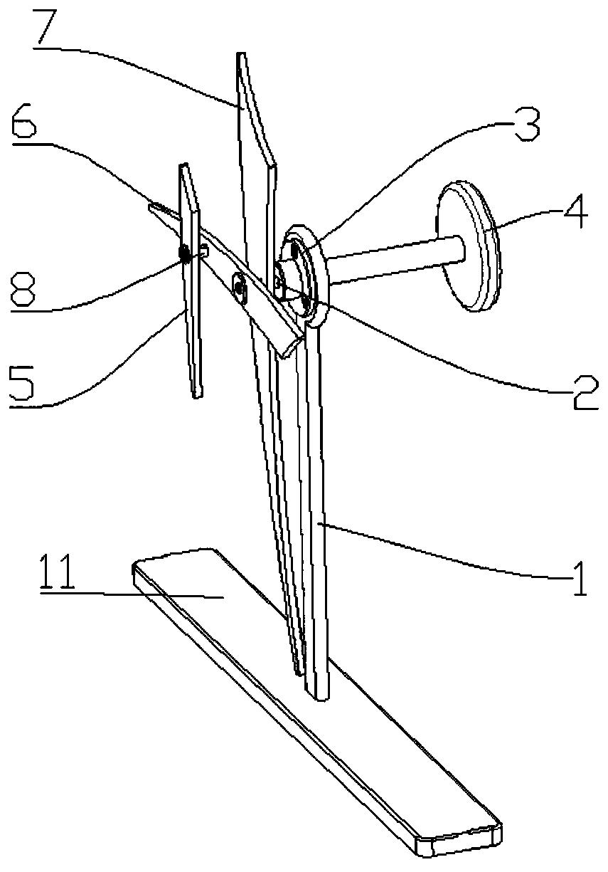
[0033] Such as figure 1As shown, the demonstration device includes a bracket 1 installed on a base 11, a main rotating shaft 2 rotating around its own axis, a first rotor blade 7 fixed on the main rotating shaft 2 and rotating synchronously with the main rotating shaft 2, and a The second rotating vane 6 on the rotating shaft 2 freely rotates around the main rotating shaft 2. The main rotating shaft 2 is mounted on the bracket 1 through the bearing seat 3. The blade surface of the second rotating vane 6 is fixed with a The main rotating shaft 2 and the auxiliary rotating shaft 8 arranged parallel to the main rotating shaft 2 are installed with the third rotating vane 5 which can freely rotate around the auxiliary rotating shaft 8 . The shaft end of the main rotating shaft 2 is provided with a rotary handle 4 for driving the main rotating shaft 2 to rotate.

[0034] The detailed description of the working process of the above-mentioned demonstration device: first, the visitor ...

Embodiment 2

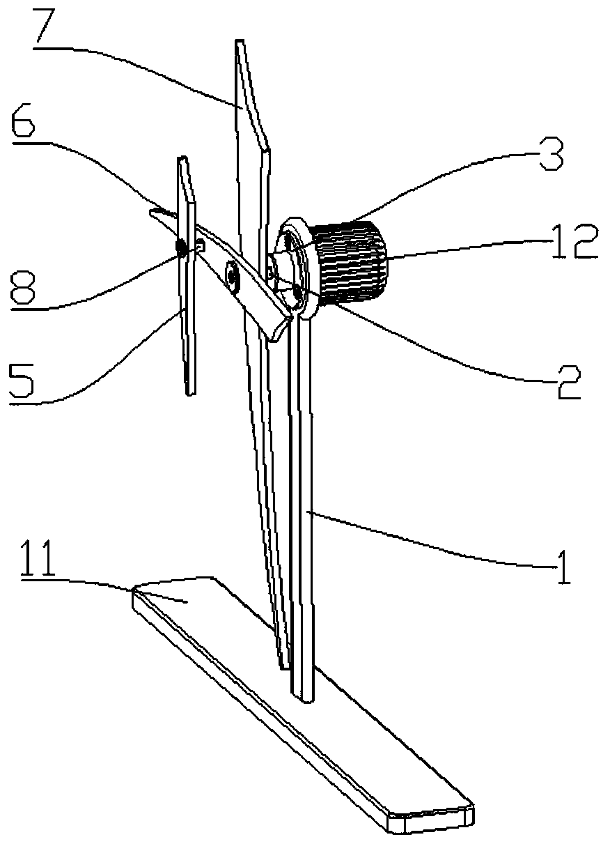
[0036] Such as figure 2 As shown, the difference from Embodiment 1 is that the end of the main rotating shaft 2 in this chaotic pendulum demonstration device is provided with a motor 12 for driving the main rotating shaft 2 to rotate.

[0037] A detailed description of the working process of the demonstration device: first, the visitor or learner starts the motor 12 momentarily and then cuts off the power, and drives the demonstration device in a clockwise or counterclockwise direction to start the demonstration: the first rotary blade 7 starts synchronously with the main rotating shaft 2 Rotate; At this time, the second rotating blade 6 has also started its own free rotation around the main rotation axis 2, and the direction and speed of rotation are inconsistent with the first rotating blade 7; meanwhile, the third rotating blade 5 It also starts its own free rotation about the secondary rotation axis 8 . During the rotation of the three rotor blades, due to the difference...

Embodiment 3

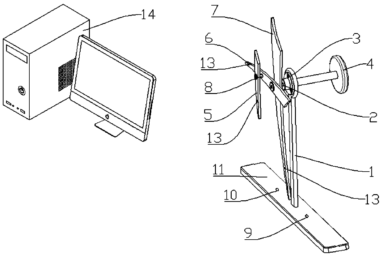
[0039] Such as image 3 As shown, the difference from Embodiment 1 is that: the base 11 is installed with a position sensor 9 and an electromagnetic driver 10 to drive the rotary vane to swing continuously. The demonstration device also includes an infrared sensor 7 installed at the tips of the first rotary vane 7, the second rotary vane 6, and the third rotary vane 5, a camera for capturing the signal of the infrared sensor, and collecting the captured signal of the camera. The received signal is processed to generate a computer 13 of a motion trajectory and a display for synchronously displaying the motion trajectory in real time. Of course, the infrared sensor 7 can be selectively installed on one or more of the first rotating vane 7 , the second rotating vane 6 and the third rotating vane 5 .

[0040] The detailed description of the working process of this demonstration device: first, visitors or learners turn the rotating handle 4 clockwise or counterclockwise, and drive...


PUM


Abstract

The invention relates to a three-blade chaotic pendulum demonstration device, which comprises a support frame, a main rotating shaft, a first rotating blade and a second rotating blade, wherein the main rotating shaft rotates around the self axial line; the first rotating blade is fixed on the main rotating shaft and does synchronous rotation along with the main rotating shaft; the second rotating blade is arranged on the main rotating shaft and does free rotation around the main rotating shaft; the main rotating shaft is arranged on the support frame through a bearing seat; the blade surface of the second rotating blade is fixedly provided with an auxiliary rotating shaft which leaves far away from the main rotating shaft and is arranged in parallel to the main rotating shaft; a third rotating blade capable of freely rotating around the auxiliary rotating shaft is arranged on the auxiliary rotating shaft. When the main rotating shaft is instantaneously driven to rotate, the rotating directions of the first rotating blade, the second rotating blade and the third rotating blade are irregular chaotic pendulum; a visitor or learner can clearly see the chaotic phenomenon shown by a chaotic pendulum mechanism; the chaotic phenomenon can be more vividly sensed; the know and the understand of people on a chaotic mechanism are enriched.

Description

technical field [0001] The invention belongs to the field of popular science education or teaching, and in particular relates to a three-leaf chaotic pendulum demonstration device. Background technique [0002] The certainty of a dynamical system is a mathematical concept, which means that the state of the system at any moment is determined by the initial state. Although the motion state at any future moment can be calculated according to the initial state data and motion laws of the motion, since the measurement of the initial state data cannot be completely accurate, errors in the predicted results are bound to occur, and even unpredictable. The predictability of motion is a physical concept. It is not contradictory that a movement can be unpredictable even if it is deterministic. The success of Newtonian mechanics, especially its success in predicting Neptune, has to a certain extent caused misunderstandings, equating certainty and predictability, thinking that determin...

Claims


Application Information

Patent Timeline
Patent Type & Authority Patents(China)
IPC IPC(8): G09B23/08G09B23/10
CPCG09B23/08G09B23/10
Inventor 李小瓯苏本林盛业涛刘卫庄李璇李瑞敏洪先亮仝文浩吉胜旺
Owner HEFEI GENERAL MACHINERY RES INST
Why Eureka
Try Eureka