End hole processing jig and clamping method of acceleration motor shell

A technology for accelerating motors and shells, which is applied in the direction of manufacturing tools, metal processing equipment, metal processing machinery parts, etc., can solve the problems of poor versatility, and achieve the effect of simple and practical structure, convenient location, and good versatility

Active Publication Date: 2018-07-13
宁波爱得信机械部件有限公司
View PDF8 Cites 0 Cited by
  • Summary
  • Abstract
  • Description
  • Claims
  • Application Information

AI Technical Summary

Problems solved by technology

[0003] The purpose of the present invention is to overcome the disadvantages that the current end hole processing jig clamps the shell of the accelerating motor to process the end hole. Provides a jig and clamping method for machining end holes of acceleration motor housings with good versatility, which can process various specifications of acceleration motor housing end holes

Method used


Image

  • End hole processing jig and clamping method of acceleration motor shell
  • End hole processing jig and clamping method of acceleration motor shell
  • End hole processing jig and clamping method of acceleration motor shell

Examples


Embodiment Construction

[0020] The present invention will be further described below in conjunction with the accompanying drawings.

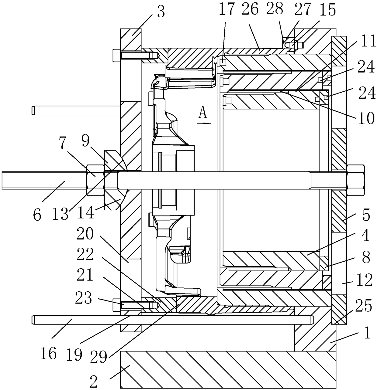
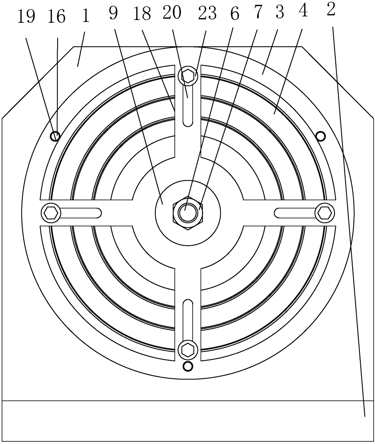
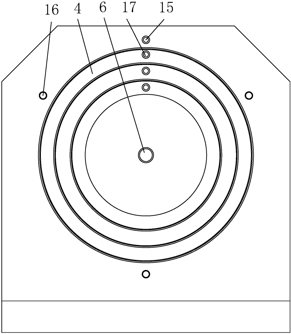
[0021] as attached figure 1 , attached figure 2 , attached image 3 Shown: a jig for processing the end hole of the acceleration motor housing, including: a base 2 with a vertical plate 1, a front pressure plate 3 with four pressing components at the rear end, and three coaxial positioning cores Cylinder 4, rear pressure plate 5, bolt 6 and fixing nut 7, locking ring 8 whose number is one less than the number of positioning core barrel 4, washer 9, positioning assembly.

[0022] The vertical plate 1 is sleeved outside the outermost positioning core barrel 4 and is screwed to the rear of the outermost positioning core barrel 4; the screw rod of the bolt 6 passes through the rear pressure plate 5, the positioning core barrel 4 and the front pressure plate 3 And be threadedly connected with fixing nut 7; Two adjacent positioning core barrels 4 are positioned at outsid...


PUM


Abstract

The invention relates to the field of machining clamps and aims at providing a clamp for acceleration motor shell end hole machining and a clamping method. The clamp for acceleration motor shell end hole machining comprises a base with a vertical plate. The clamp for acceleration motor shell end hole machining further comprises a front platen with multiple pressing assemblies at the rear end, multiple positioning core cylinders arranged in a coaxially sleeving manner, a rear platen, a bolt, a fixed nut and a positioning assembly. The outmost positioning core cylinder is sleeved with the vertical plate. The vertical plate is connected with the rear portion of the outmost positioning core cylinder. A screw of the bolt penetrates the rear platen, the positioning core cylinders and the front platen and is connected with the fixed nut in a threaded manner. The outer positioning core cylinder in every two adjacent positioning core cylinders is provided with an adjusting screw hole and rear end of the other inner positioning core cylinder is provided with a protruding ring connected with the corresponding adjusting screw hole in a threaded manner. By the adoption of the clamp for acceleration motor shell end hole machining, end holes of acceleration motor shells of various specifications can be machined, and universality is good.

Description

technical field [0001] The invention relates to the field of machining fixtures, in particular to a fixture and a clamping method for machining an end hole of an acceleration motor housing. Background technique [0002] The flange of the accelerating motor shell is provided with end holes that need to be processed; the traditional end hole processing fixture clamps the shell of the accelerating motor for end hole processing, and there is a processing fixture that can only process the end of the accelerating motor shell of one specification. Therefore, it is urgent to design a jig and clamping method for processing the end holes of the acceleration motor housing with good versatility, which can process the end holes of the acceleration motor housing of various specifications The problem. Contents of the invention [0003] The purpose of the present invention is to overcome the disadvantages that the current end hole processing jig clamps the shell of the accelerating motor...

Claims


Application Information

Patent Timeline
Patent Type & Authority Patents(China)
IPC IPC(8): B23Q3/06
CPCB23Q3/062
Inventor 顾继跃陆琦
Owner 宁波爱得信机械部件有限公司
Why Eureka
Try Eureka