Ceramic thrust bearing assembly and water-lubricated screw compressor

A technology of screw compressor and thrust bearing, applied in the direction of bearing components, rigid brackets of bearing components, bearings, etc., can solve the problems of expensive ceramic bearing materials, high brittleness of ceramic bearings, economic losses, etc., so as to reduce the risk of damage and improve the Service life and the effect of improving assembly efficiency

Pending Publication Date: 2022-01-14
NINGBO BAOSI ENERGY EQUIP
View PDF0 Cites 0 Cited by
  • Summary
  • Abstract
  • Description
  • Claims
  • Application Information

AI Technical Summary

Problems solved by technology

[0002] As a completely oil-free compressor, water-lubricated screw compressors are widely used in petroleum, chemical, food, pharmaceutical and other fields, in line with the development trend of the market. At present, the water-lubricated bearings used on screw rotors generally use ceramic bearings. It has the characteristics of high temp

Method used


Image

  • Ceramic thrust bearing assembly and water-lubricated screw compressor
  • Ceramic thrust bearing assembly and water-lubricated screw compressor
  • Ceramic thrust bearing assembly and water-lubricated screw compressor

Examples


Embodiment 1

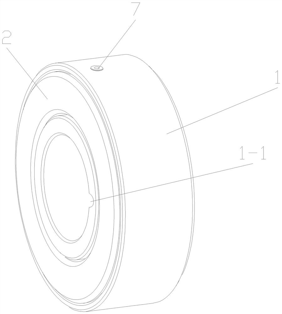
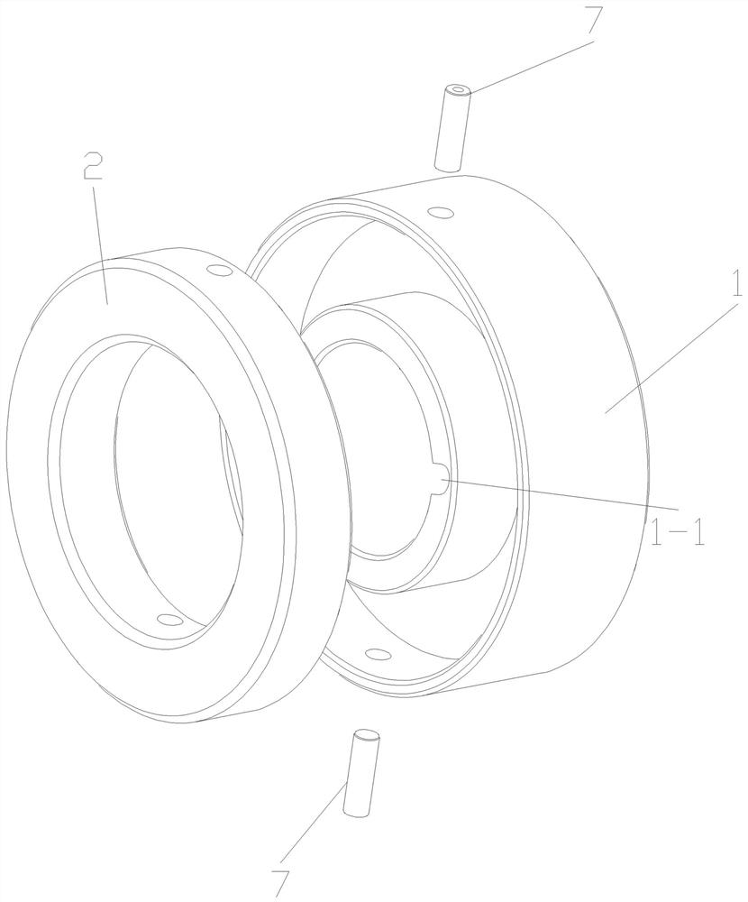
[0024] Such as figure 1 with figure 2 As shown in , the ceramic thrust bearing assembly of the present invention includes a thrust bearing housing 1, a ceramic thrust bearing 2 and two thrust bearing positioning pins 7, and the ceramic thrust bearing 2 is ceramic made of silicon carbide, zirconia, silicon nitride and other materials Bearing, thrust bearing housing 1 is made of stainless steel and other materials that are not easily corroded by water. Both thrust bearing housing 1 and ceramic thrust bearing 2 are of annular structure, and thrust bearing housing 1 is provided with an annular groove for installing ceramic thrust bearing 2. 2 is limited between the side wall of the inner ring and the side wall of the outer ring of the annular groove, one end surface and two annular side walls of the ceramic thrust bearing 2 are wrapped in the annular groove, and the working end surface of the ceramic thrust bearing 2 is convex Out of the annular groove, the thrust bearing seat 1...

Embodiment 2

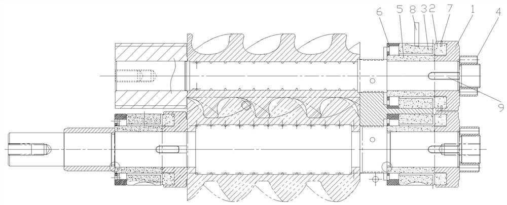
[0026] Such as image 3As shown in , the water-lubricated screw compressor of the present invention includes a compressor host, a screw rotor is arranged in the cylinder of the compressor host, and a bearing hole is arranged on the casing of the compressor host, and the bearing hole is provided with a The ceramic thrust bearing assembly described in Example 1 also includes a ceramic bushing 3, a ceramic bushing 5, and a spring mounting seat 6. A wave spring is arranged in the spring mounting seat 6, and the ceramic bushing 5, the ceramic bushing 3, and the ceramic thrust bearing 2 They are all made of ceramic material. In this embodiment, silicon carbide material is used, and zirconia material can also be used; the spring mounting seat 6, the ceramic bushing 5, and the thrust bearing seat 1 are all sleeved on the screw rotor, and the spring mounting seat 6 is limited. On the inner side of the bearing hole, the inner side of the ceramic bushing 5 is also provided with a keyway,...


PUM


Abstract

The invention relates to a ceramic thrust bearing assembly and a water-lubricated screw compressor. The ceramic thrust bearing assembly comprises a thrust bearing seat and a ceramic thrust bearing, the thrust bearing seat and the ceramic thrust bearing are both of an annular structure, and the thrust bearing seat is provided with an annular groove used for installing the ceramic thrust bearing; and the ceramic thrust bearing is limited between the side wall of the inner ring and the side wall of the outer ring of the annular groove, one end face and the two annular side walls of the ceramic thrust bearing are all wrapped in the annular groove, the other end face of the ceramic thrust bearing protrudes out of the annular groove, and the thrust bearing seat is detachably connected with the ceramic thrust bearing. The thrust bearing seat can well protect the ceramic thrust bearing, the damage risk of the ceramic thrust bearing is reduced, the service life of the ceramic thrust bearing is effectively prolonged, and the production cost is reduced.

Description

technical field [0001] The invention relates to the technical field of oil-free compressors, in particular to a ceramic thrust bearing assembly and a water-lubricated screw compressor. Background technique [0002] As a completely oil-free compressor, water-lubricated screw compressors are widely used in petroleum, chemical, food, pharmaceutical and other fields, in line with the development trend of the market. At present, the water-lubricated bearings used on screw rotors generally use ceramic bearings. It has the characteristics of high temperature resistance, wear resistance, corrosion resistance, oil-free self-lubrication, high speed, etc., but ceramic bearings are brittle. If the force is not uniform during application, the local stress will be too concentrated and cause damage and fracture. Bearing materials are expensive, and once damaged, it will cause large economic losses. Contents of the invention [0003] The technical problem to be solved by the present inve...

Claims


Application Information

Patent Timeline
IPC IPC(8): F16C17/08F16C33/04F16C35/02F04C29/00
CPCF16C17/08F16C33/043F16C35/02F04C29/00F04C2240/50F16C2360/43
Inventor 周坤马升庄博胡伟
Owner NINGBO BAOSI ENERGY EQUIP
Why Eureka
Try Eureka