Mechanical transmission unit of engineering drawing universal projection demonstration device

A technology of mechanical transmission and demonstration device, which is applied in the field of mechanical transmission units, can solve the problems of expressing the core concept of universal projection, limited teaching aid storage and demonstration content, and inconvenient teaching of universal projection, so as to achieve good understanding, good teaching effect, and use flexible effects

Inactive Publication Date: 2016-12-21
NORTHEAST FORESTRY UNIVERSITY
View PDF8 Cites 2 Cited by
  • Summary
  • Abstract
  • Description
  • Claims
  • Application Information

AI Technical Summary

Problems solved by technology

[0004] The purpose of the present invention is to solve the problem that existing teaching aids have limited demonstration content, and the projection display is limited to LED dis

Method used


Image

  • Mechanical transmission unit of engineering drawing universal projection demonstration device
  • Mechanical transmission unit of engineering drawing universal projection demonstration device
  • Mechanical transmission unit of engineering drawing universal projection demonstration device

Examples


specific Embodiment approach 1

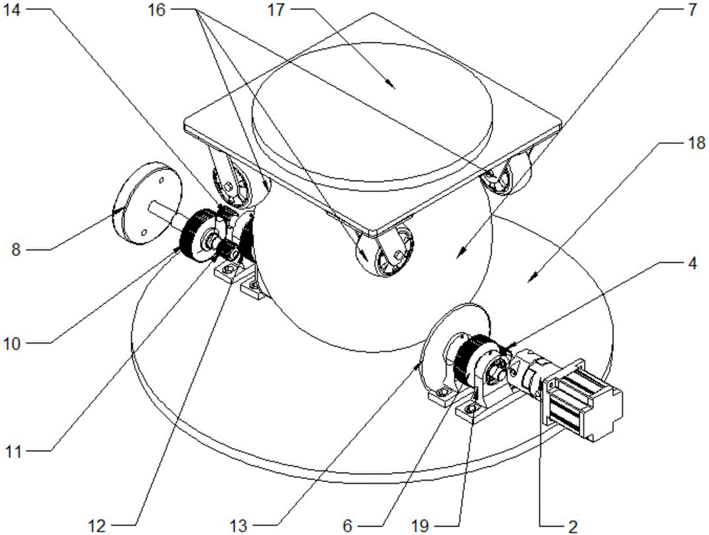
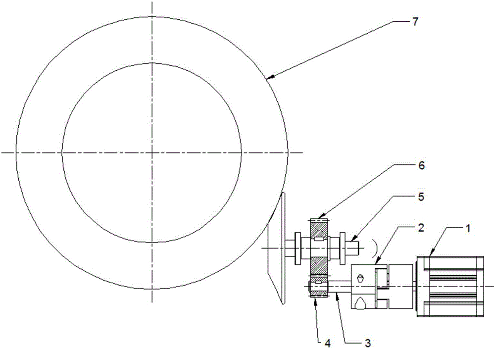
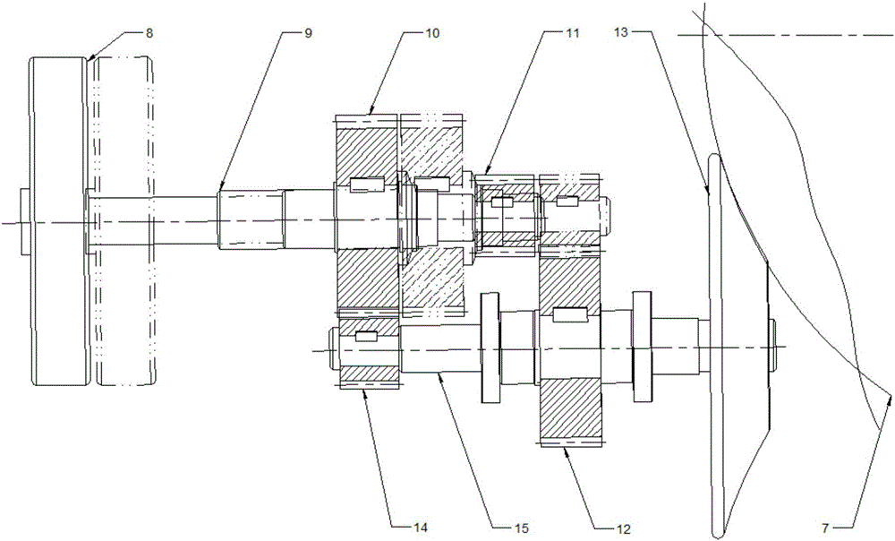
[0027] Specific implementation mode one: combine Figure 1 to Figure 6 Describe this embodiment, the mechanical transmission unit of a kind of universal projection demonstration device of engineering drawing of this embodiment comprises base plate 18, fixed plate 17, projection mechanism 7, drive mechanism, adjustment mechanism and a plurality of universal wheels 16, fixed plate 17 Arranged in parallel with base plate 18 up and down, projection mechanism 7 is installed between fixed plate 17 and base plate 18, the top of projection mechanism 7 is slidably positioned by a plurality of universal wheels 16 installed on the lower end of fixed plate 17, both sides of projection mechanism 7 It is in contact with the driving mechanism and the adjusting mechanism installed on the bottom plate 18, and the driving mechanism and the adjusting mechanism drive the projection mechanism 7 to rotate.

specific Embodiment approach 2

[0028] Specific implementation mode two: combination figure 1 The present embodiment will be described. The projection mechanism 7 of the present embodiment is a one-way see-through hollow glass ball. Such setting avoids the influence of external light on the projection demonstration process. Other compositions and connections are the same as in the first embodiment.

specific Embodiment approach 3

[0029] Specific implementation mode three: combination figure 1 To illustrate this embodiment, the one-way perspective hollow ball of this embodiment is cut by a plane at 1 / 2 of the diameter and at 2 / 15 of the diameter, and is divided into three parts, all of which are screwed together to form a complete hollow ball . In this way, the disassembly at the radius is to facilitate the installation of the inner parts of the ball and subsequent maintenance and inspection, and the disassembly at 2 / 15 is convenient for the placement of the spotlight and the placement of the model during operation. Other compositions and connections are the same as those in Embodiment 1 or Embodiment 2.


PUM


Abstract

The invention relates to a mechanical transmission unit, in particular to a mechanical transmission unit of an engineering drawing universal projection demonstration device. In order to solve the problems that the existing teaching aid is limited in demonstration content, the projection is restricted to LED display, the core idea of universal projection cannot be expressed appropriately, and inconvenience is brought for the teaching of engineering drawing in the aspect of universal projection, the mechanical transmission unit is provided. The mechanical transmission unit comprises a fixed plate (17) and a bottom plate (18), wherein the fixed plate (17) and the bottom plate (18) are arranged in parallel in the vertical direction, a projection mechanism (7) is arranged between the fixed plate (17) and the bottom plate (18), the upper part of the projection mechanism (7) can be positioned in a sliding manner by means of a plurality of universal wheels (16) installed at the lower end of the fixed plate (17), two sides of the projection mechanism (7) are in contact with a driving mechanism and an adjusting mechanism installed on the bottom plate (18), and the driving mechanism and the adjusting mechanism drive the projection mechanism (7) to rotate. The mechanical transmission unit is used for engineering drawing universal projection demonstration.

Description

technical field [0001] The invention relates to a component unit of a projection demonstration device, in particular to a mechanical transmission unit of an engineering drawing universal projection demonstration device. Background technique [0002] The traditional engineering drawing teaching in my country is mainly based on blackboard writing, paper wall charts and a single physical model, but the above teaching aids are obviously insufficient in the teaching process. For example, blackboard writing is indispensable in teaching, but it will take a long time for teachers to draw on the blackboard, and the output of classroom knowledge will be correspondingly reduced; traditional paper wall charts can relieve the time pressure brought by teachers’ drawing on blackboard during the teaching process. However, the number of example questions on the paper wall chart is limited and cannot be changed flexibly; the structure of the physical model is single, and each model can only e...

Claims


Application Information

Patent Timeline
IPC IPC(8): G09B5/02
CPCG09B5/02
Inventor 冯奕畅张兴丽王松袁晓康宁礼佳王程琦
Owner NORTHEAST FORESTRY UNIVERSITY
Why Eureka
Try Eureka