
Single-ended protection method for multi-terminal flexible DC grid system based on boundary characteristics

A multi-terminal flexible, DC power grid technology, applied in the direction of emergency protection circuit devices, electrical components, etc., can solve problems such as difficult fault identification, and achieve the effects of strong protection applicability, cost saving, and fast protection action

Active Publication Date: 2019-01-11
TIANJIN UNIV
View PDF4 Cites 2 Cited by
  • Summary
  • Abstract
  • Description
  • Claims
  • Application Information

AI Technical Summary

Problems solved by technology

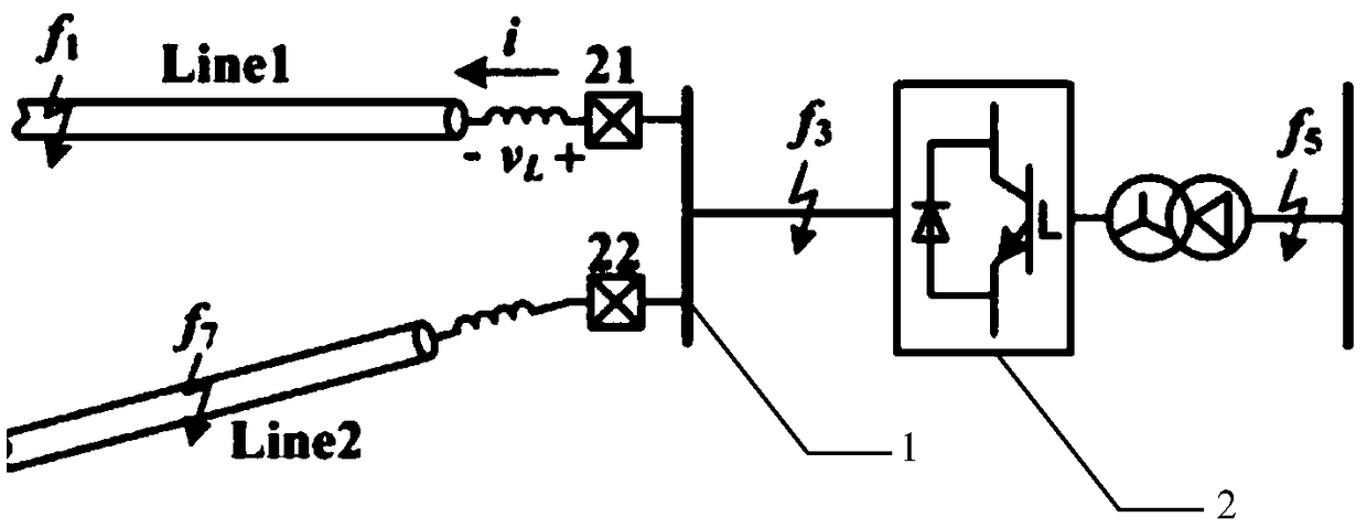
[0004] Aiming at the difficulty of fault identification in the multi-terminal flexible DC power grid and the shortcomings of the current traditional AC system and conventional HVDC transmission system protection principles directly applied to the multi-terminal flexible DC distribution network, the present invention proposes a multi-terminal flexible DC power grid based on boundary characteristics The single-ended quantity protection method of the system proposes a new type of single-ended quantity protection scheme that uses the voltage drop of the DC reactor to determine the direction and identifies the fault through high-frequency transient energy, so as to realize the rapid and reliable identification of the fault

Method used


Image

  • Single-ended protection method for multi-terminal flexible DC grid system based on boundary characteristics
  • Single-ended protection method for multi-terminal flexible DC grid system based on boundary characteristics
  • Single-ended protection method for multi-terminal flexible DC grid system based on boundary characteristics

Examples


Embodiment Construction

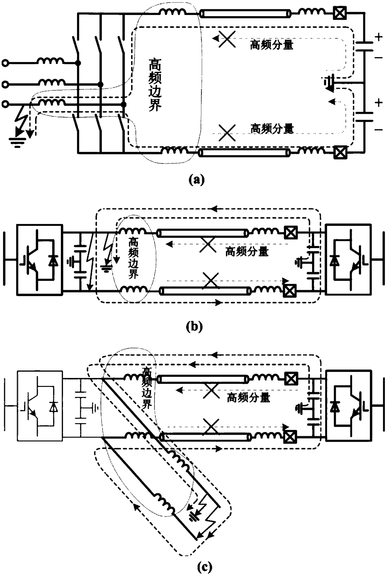
[0025] like figure 1 As shown, there are various forms of equivalent circuit diagrams when the protected DC line of the multi-terminal flexible DC power grid has an out-of-area fault, and the present invention lists three equivalent circuits among them. Wherein, the smoothing reactor installed at the outlet of the converter is used as the high-frequency energy boundary in the present invention. When a fault occurs, the smoothing reactor will show a very large impedance value for the middle and high frequency band of the fault current, thereby affecting High-frequency components play a blocking role. Therefore, when a fault occurs outside the zone, the high-frequency component is blocked by the high-frequency boundary, and the high-frequency component in the zone is small; while when a fault occurs in the zone, the high-frequency component in the zone is relatively large because there is no high-frequency barrier. Therefore, transient energy (that is, high-frequency component ...


PUM


Abstract

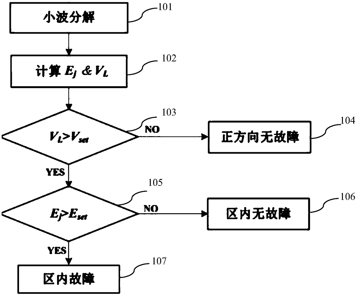
The invention discloses a boundary-characteristic-based non-unit protection method for a multi-terminal flexible direct-current power grid system. The method comprises: wavelet decomposition is carried out to extract a high-frequency component in a fault current; a high-frequency transient energy value Ej and a voltage drop VL on a smoothing reactor of the fault current are calculated; a fault direction is determined by using the voltage drop VL on the smoothing reactor; if no fault occurs in a positive direction, exit from a fault protection process is carried out; if a fault occurs in the positive direction, whether a fault occurs in a region is determined by using the high-frequency transient energy Ej criterion; if a condition that the Ej is larger than an Eset value is met, the in-region fault is determined and the fault protection action is executed; and otherwise, no fault in a region is determined and exit from a fault protection process is carried out. Compared with the prior art, rapid fault identification can be realized within a few of milliseconds and the protection action is carried out rapidly. Moreover, fault determination and identification are carried out only by using the electric quantity at the terminal without communication with other convertor stations, so that the costs are lowered. The method has the high anti-transition-resistance capability and the protection applicability is high.

Description

technical field [0001] The invention relates to the field of power system protection and control, and proposes a multi-terminal flexible DC power grid DC line protection scheme. Background technique [0002] Fast and reliable identification of DC faults is a key technology for the development of flexible DC grids. For the multi-terminal flexible DC power grid, when a DC fault occurs in any part of the DC field, due to the small impedance of the DC line and the interconnection of the converter stations and the DC lines, each DC line will rapidly appear different degrees of overcurrent phenomenon, and the fault overcurrent It will affect the safe and reliable operation of the entire DC system, so the protection of the multi-terminal flexible DC grid puts forward high requirements for the ability to quickly and reliably identify faults. [0003] In DC systems, traditional fault protection includes overcurrent protection, distance protection, and traveling wave protection. How...

Claims


Application Information

Patent Timeline
Patent Type & Authority Patents(China)
IPC IPC(8): H02H7/26
CPCH02H7/268
Inventor 李斌邱宏何佳伟
Owner TIANJIN UNIV
Learn More