
Adjustable motor base

A motor base, adjustable technology, applied in the direction of electrical components, electromechanical devices, electric components, etc., can solve the problems of shortening the service life of the belt, not adjusting the belt in time, and overheating the belt, so as to achieve convenient installation, time-saving adjustment and maintenance, The effect of structural stabilization

Inactive Publication Date: 2016-12-21
张振堂
View PDF4 Cites 6 Cited by
  • Summary
  • Abstract
  • Description
  • Claims
  • Application Information

AI Technical Summary

Problems solved by technology

[0002] For belt-driven equipment, especially V-belt drive, only when the belt reaches the optimal tension state can the required torque be effectively transmitted to the driven equipment, so the belt-driven equipment needs a motor that can adjust the position The device, and the tension of the belt is not adjusted in time during installation and use, resulting in a decrease in torque, overheating of the belt, and harsh noises, and the service life of the belt is also greatly reduced; therefore, providing a stable structure and easy installation , it is very necessary to adjust and maintain an adjustable motor base that saves time and effort

Method used


Image

  • Adjustable motor base
  • Adjustable motor base
  • Adjustable motor base

Examples


Embodiment 1

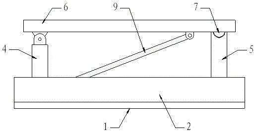
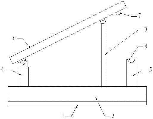
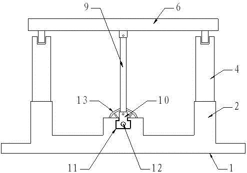
[0017] Such as Figure 1-4 As shown, an adjustable motor base, which includes a base 1, two parallel vertical plates 2 are arranged on the upper side of the base 1, and a bar-shaped hole 3 for installation is provided on the lower part of the base 1 The middle part of the upper side of the base 1 is provided with a chute 11, one end of the upper side of the vertical plate 2 is provided with a hinged column 4, and the other end is provided with a positioning column 5, and the upper end of the hinged column 4 is hinged with a motor plate 6, the upper side of the positioning column 5 is provided with a positioning groove 8, the four corners of the motor plate 6 are provided with motor mounting holes 14, and the lower side of the end of the motor plate 6 is provided with a positioning groove 8 Cooperating positioning protrusion 7, the end of near positioning protrusion 7 on the lower side of the motor plate 6 is hinged with a drive link 9, the lower end of the drive link 9 is hing...

Embodiment 2

[0020] Such as Figure 1-4 As shown, an adjustable motor base, which includes a base 1, two parallel vertical plates 2 are arranged on the upper side of the base 1, and a bar-shaped hole 3 for installation is provided on the lower part of the base 1 The middle part of the upper side of the base 1 is provided with a chute 11, one end of the upper side of the vertical plate 2 is provided with a hinged column 4, and the other end is provided with a positioning column 5, and the upper end of the hinged column 4 is hinged with a motor plate 6, the upper side of the positioning column 5 is provided with a positioning groove 8, the four corners of the motor plate 6 are provided with motor mounting holes 14, and the lower side of the end of the motor plate 6 is provided with a positioning groove 8 Cooperating positioning protrusion 7, the end of near positioning protrusion 7 on the lower side of the motor plate 6 is hinged with a drive link 9, the lower end of the drive link 9 is hing...


PUM


Abstract

The invention relates to an adjustable motor base which comprises a base. The adjustable motor base is characterized in that the upper side of the base is provided with two parallel vertical plates, the lower part of the base is provided with a bar-shaped hole, the middle part of the upper side of the base is provided with a slide chute, one end of the upper side of the vertical plate is provided with a hinge column, the other end is provided with a positioning column, the upper end of the hinge column is hinged to a motor plate, the upper side of the positioning column is provided with a positioning groove, the four corners of the motor plate are provided with motor mounting holes, the lower side of the end of the motor plate is provided with a positioning projection which is matched with the positioning groove, one end of the lower side of the motor plate near the positioning projection is hinged to a driving connection rod whose lower end is hinged to a sliding block which slides along the slide chute, the center part of the slide block is provided with a screw rod which goes trough the slide block, and one end of the screw rod is connected to a handwheel. The adjustable motor base has the advantages of a stable structure, convenient installation, and labour saving and time saving of adjustment and maintenance.

Description

technical field [0001] The invention relates to a motor base, in particular to an adjustable motor base. Background technique [0002] For belt-driven equipment, especially V-belt drive, only when the belt reaches the optimal tension state can the required torque be effectively transmitted to the driven equipment, so the belt-driven equipment needs a motor that can adjust the position The device, and the tension of the belt is not adjusted in time during installation and use, resulting in a decrease in torque, overheating of the belt, and harsh noise, and the service life of the belt is also greatly reduced; therefore, providing a stable structure and easy installation , It is very necessary to adjust and maintain an adjustable motor base that saves time and effort. Contents of the invention [0003] The purpose of the present invention is to overcome the deficiencies of the prior art and provide a crane movable cab with reasonable structure, safety and stability. [000...

Claims


Application Information

Patent Timeline
IPC IPC(8): H02K5/26
CPCH02K5/26
Inventor 张振堂
Owner 张振堂
Learn More