Portable 3D printer
A 3D printer, portable technology, applied in the direction of additive processing, etc., can solve the problems of inability to fold, large volume, high cost, etc., achieve the effect of compact structure design and reduce manufacturing cost
- Summary
- Abstract
- Description
- Claims
- Application Information
AI Technical Summary
Problems solved by technology
Method used
Image
Examples
example 1 00
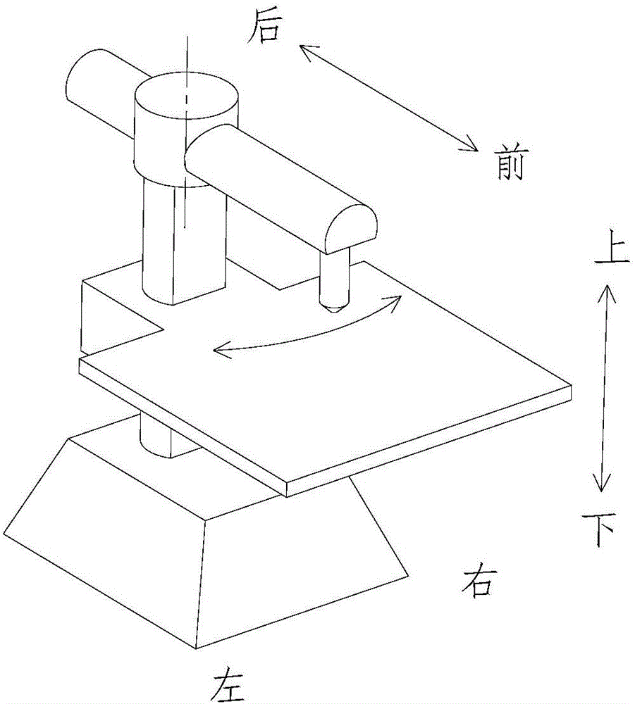
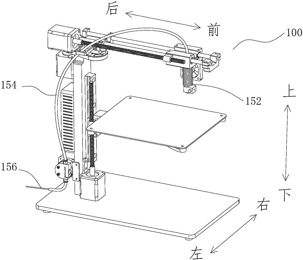
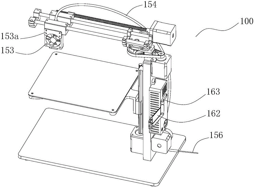
[0073] like Figure 2-1 and Figure 2-4 As shown, the frame includes a column 111 and a bottom plate 112. The column 111 is a strip-like object with a rectangular cross-section stretched along the up-down direction.
[0074] The 3D printer lifting device is composed of a guide rail 141, a slider 142, a platform support 143, a printing platform 144 and a motor drive mechanism. The guide rail 141 is a linear guide rail fixed on the front surface of the column 111 parallel to the longitudinal direction of the column 111. The slide block 142 slides on the guide rail 141, and the front surface of the slide block 142 is parallel to the sliding direction. The platform support 143 is an "L"-shaped cantilever structure viewed from the left side. The plane at the rear is matched and fixed to the front surface of the slider 142. The upper part is fixedly connected with the printing platform 144. The upper surface of the printing platform 144 is connected to the The planes at the rear o...
example 2 01
[0079] On the basis of the 3D printer example 100, the innovative design of the bottom plate and the platform bracket enables the 3D printer to realize the folding function; the change of the rotating arm and the nozzle movement device can realize another compact structure; increasing the number of nozzles makes the The 3D printer realizes functions such as support printing, multi-color and multi-material printing.
[0080] Specifically, at least three elongated legs 113 are used, and the bottom of the column 111 is rotatably connected to one end of the leg 113, and the axis of rotation is parallel to the length direction of the column 111. Preferably, as Figure 3-4 As shown, three supporting legs 113 are used, all of which are elongated. The bottom surface of one end is provided with a foot pad 114 at the lowest point, and the other end is provided with a stepped hole penetrating the surface along the up and down direction, and the fastener 115 passes through the step. The h...
example 1 00
[0089]In order to make the carrying of the 3D printer more convenient, a carrying case is designed on the basis of the 3D printer example 2 101. The design of the carrying case requires the folded 3D printer to be firmly and reliably restrained inside the carrying case, so that it will not be bumpy during transportation. And the vibration makes the printer parts shake; further carrying cases also need to integrate printing rolls, which saves the inconvenience of additional carrying; further carrying cases also need to integrate batteries, so that the 3D printer can be used without a fixed power supply or in the field still work.
[0090] The box body includes an upper box body 211 and a lower box body 212. The upper box body 211 and the lower box body 212 cooperate to form a space for accommodating a 3D printer with the legs 113 in a folded state and the printing platform 144 in a folded state. Specifically, if Pic 4-1 As shown, the box body is composed of an upper box body ...
PUM
 Abstract
Description
Claims
Application Information
 - R&D
- Intellectual Property
- Life Sciences
- Materials
- Tech Scout
- Unparalleled Data Quality
- Higher Quality Content
- 60% Fewer Hallucinations
Browse by: Latest US Patents, China's latest patents, Technical Efficacy Thesaurus, Application Domain, Technology Topic, Popular Technical Reports.
© 2025 PatSnap. All rights reserved.Legal|Privacy policy|Modern Slavery Act Transparency Statement|Sitemap|About US| Contact US: help@patsnap.com


