Laser marking positioning device and building snapping line marking positioning method

A positioning device and laser marking technology, applied in the direction of measuring point marking, etc., can solve the problems of unfavorable identification and insufficient accuracy of marking position, and achieve the effect of rapid adjustment

Active Publication Date: 2017-01-04
CHINA CONSTR EIGHT ENG DIV CORP LTD
View PDF5 Cites 3 Cited by
  • Summary
  • Abstract
  • Description
  • Claims
  • Application Information

AI Technical Summary

Problems solved by technology

[0004] In view of the above situation, the present invention provides a laser marking positioning device and a construction spring line marking positioning method thereof. By setting a fixed-length leg on the laser marking positioning device, it is used to abut against the wall, so as to accurately measure the spring The distance from the wall of the line position; in addition, by setting the first wavelength laser and at least two second wavelength lasers, the intersection of the laser line output by the first wavelength laser and the laser line output by the at least two second wavelength lasers generates at least two focal points , to solve the technical problems of insufficient mark position accuracy in the existing manual spring line marking and unfavorable for identification in dark places, so that the laser marking positioning device of the present invention can be conveniently, quickly and accurately used in various ground line operations that require

Method used


Image

  • Laser marking positioning device and building snapping line marking positioning method
  • Laser marking positioning device and building snapping line marking positioning method
  • Laser marking positioning device and building snapping line marking positioning method

Examples


Embodiment Construction

[0035] In order to facilitate the understanding of the present invention, the following will be described in conjunction with the accompanying drawings and embodiments.

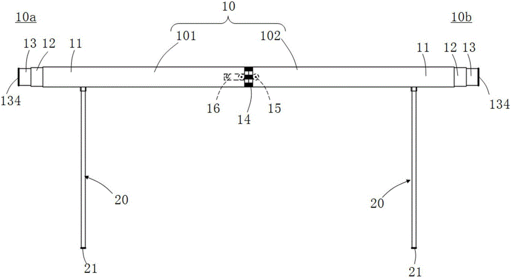
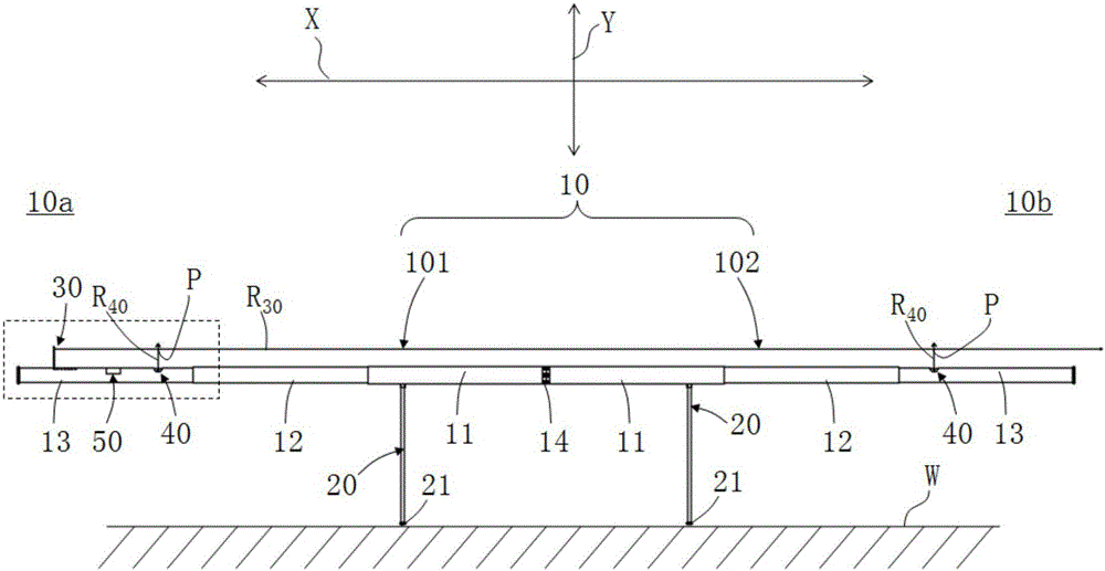
[0036] see Figure 1 to Figure 6 , the present invention provides a laser marking positioning device, which includes a main support 10 , at least two legs 20 , a first wavelength laser 30 , at least two second wavelength lasers 40 and a power supply module 50 . in:

[0037] Such as figure 1 , figure 2 , the main bracket 10 has an opposite first end 10a and a second end 10b, the first end 10a is formed by a first telescopic rod 101, and the second end 10b is formed by a second telescopic rod 102; The first telescopic rod 101 includes an intermediate rod 11, a connecting rod 12 and an end rod 13 which are nested in each other, and the second telescopic rod 102 also includes an intermediate rod 11 and a connecting rod which are nested in each other. 12 and a terminal rod 13.

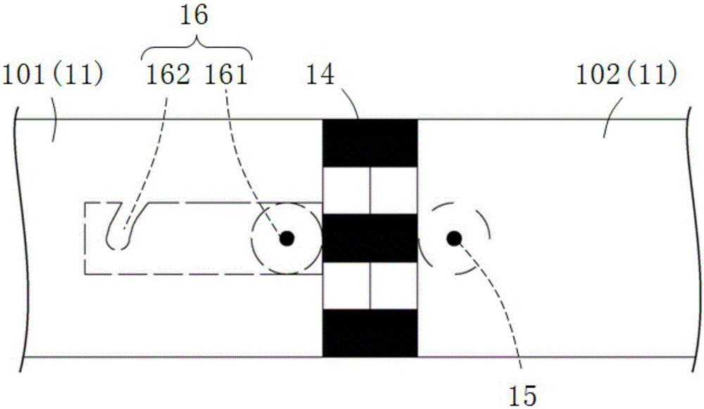
[0038] Such as image 3 , ...


PUM


Abstract

The invention provides a laser marking positioning device and a building snapping line marking positioning method. The device comprises a main support frame, a first wavelength laser and at least two second wavelength lasers, wherein the main support frame is provided with two opposite sides; at least two support feet are arranged at one side; the main support frame extending direction is defined to be the first direction; the first wavelength laser is arranged at the other side of the main support frame relative to the support feet, and outputs a first laser line along the first direction; the at least two wavelength lasers are arranged at the other side of the main support frame relative to the support feet, and output second laser lines; the second laser lines and the first laser line are intersected to form at least two focal points. Through the device, the distance from the wall is determined; at least two laser line focal points are generated, so that the line snapping by an inking pot is performed at the focal points of the laser lines. The distance from the snapping line position to the all can be accurately measured; the laser marking positioning device can be conveniently, fast and accurately used in various kinds of application with line snapping requirements.

Description

technical field [0001] The present invention relates to the technical field of building elastic thread, in particular to a marking positioning device for elastic thread and a marking positioning method for elastic thread. Background technique [0002] Thread snapping is a method of construction work. The specific operation method is: use a thread dipped in ink, two people each take one end and bounce it on the ground or wall. The function is to determine the horizontal line or vertical line, or as a reference line for building walls. Among them, the ground wire refers to the tool line used to mark the clear height of the room and the depth of the bay in the process of building household acceptance. The ground wire is generally used in residential building construction. [0003] As a basic link in building construction, snapping wire has very high requirements for its accuracy in construction, because it will determine the success or failure of the next process. It is worth...

Claims


Application Information

Patent Timeline
Patent Type & Authority Applications(China)
IPC IPC(8): G01C15/02
CPCG01C15/02
Inventor 孟吉哲潘兴华刘涛雷克白洁张宇
Owner CHINA CONSTR EIGHT ENG DIV CORP LTD
Why Eureka
Try Eureka