A method and system for remote monitoring of fire fighting equipment

A firefighting equipment and remote monitoring technology, applied in fire alarms, instruments, fire rescue, etc., can solve the problems of missed rescue time, unfavorable equipment operation and maintenance, mastering fire information, etc. maintenance effect

Active Publication Date: 2018-06-12
FUZHOU CHUANDA SOFTWARE TECH
View PDF7 Cites 0 Cited by
  • Summary
  • Abstract
  • Description
  • Claims
  • Application Information

AI Technical Summary

Problems solved by technology

However, there are two problems in the existing methods and systems for networked centralized monitoring of fire-fighting equipment: one is that different brands of fire-fighting hosts are difficult to be compatible; Monitor and obtain equipment operation status, which is not conducive to equipment operation and maintenance
[0003] At present, the fire fighting system relies heavily on the way of human alarm, and the fire situation, location and other related information need to be described manually. This situation varies with the quality of the on-duty personnel. It is difficult for personnel to grasp the fire information at the first time, resulting in missing the best rescue time

Method used


Image

  • A method and system for remote monitoring of fire fighting equipment
  • A method and system for remote monitoring of fire fighting equipment
  • A method and system for remote monitoring of fire fighting equipment

Examples


Embodiment 1

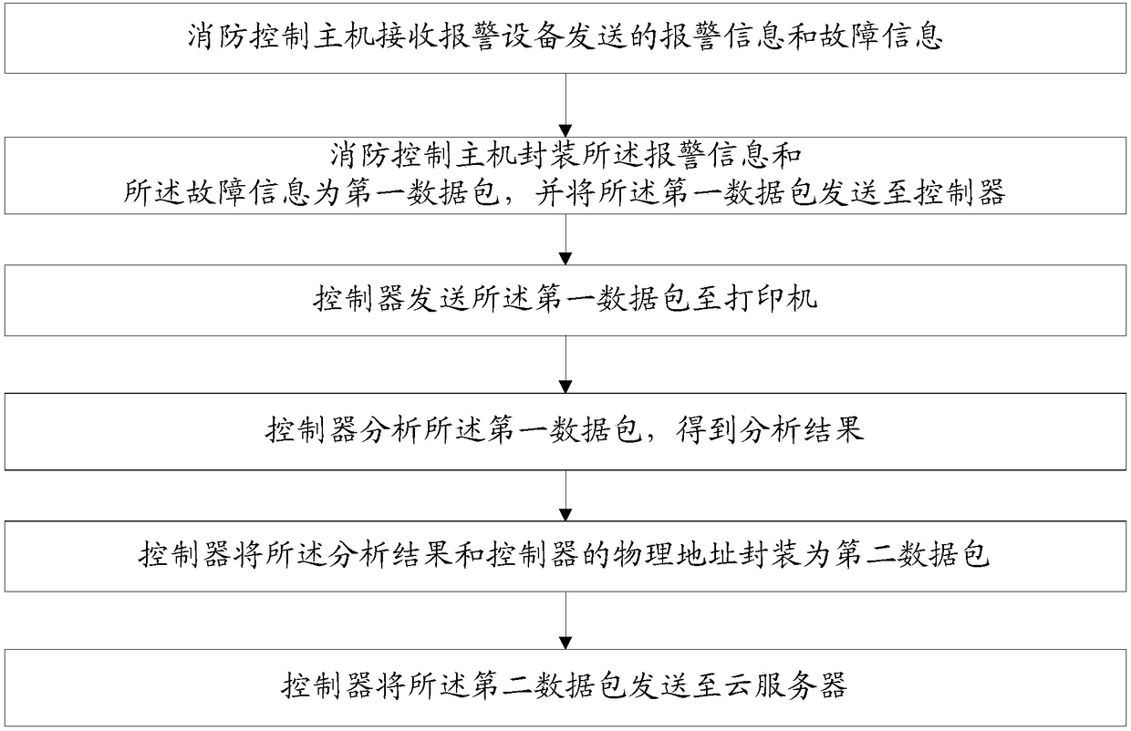
[0084] The fire control host receives the alarm information and fault information sent by the alarm equipment;

[0085] The fire control host encapsulates the alarm information and the fault information into a first data packet;

[0086] The controller judges whether the printer is in an idle state;

[0087] If yes, the controller notifies the fire control host to send the first data packet;

[0088] Otherwise, start timing and get the waiting time; if the waiting time exceeds the threshold, the controller will notify the fire control host to send the first data packet; otherwise, continue to time;

[0089] Sending the first data packet to the controller;

[0090] The controller forwards the first data packet to the printer;

[0091] Parse the first data packet to obtain an event set;

[0092] Identify the dot matrix in the event set to obtain event specific information; the event specific information includes event type and channel number;

[0093] Encapsulating the specific information of...

Embodiment 2

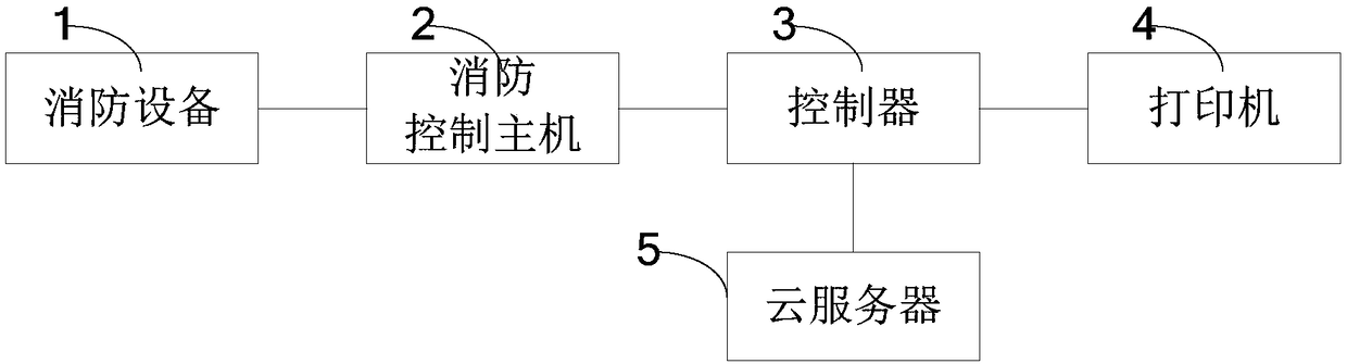
[0105] Connect the controller in series between the LN1010 fire control host and the SPRMA printer, and connect the communication interface of the controller to the cloud server. When an LN1010 fire control host has an alarm in the fire centralized monitoring system, the LN1010 fire control host will send the fire alarm information, power failure information and fire protection equipment failure information to the controller, and the LN1010 fire control host detects the control When the device is in an idle state, immediately put the data to be sent on the port, and then use a rising edge trigger signal to notify the controller to read the data of the port, so that the print information is sent out byte by byte reciprocally. When the controller receives the data, it will forward the data just received to the SPRMA printer. When the LN1010 fire control host has no data to send, the controller can process the received data. Through data matching, it is known that the event type s...


PUM


Abstract

The invention relates to the field of intelligent monitoring, in particular to a method and system for remotely monitoring fire-fighting equipment. The present invention monitors the fire-fighting equipment in the same building by using the fire-fighting control host, obtains the alarm information and fault information sent by the fire-fighting equipment, and forwards the alarm information and fault information to the controller in the building in real time, and the controller transmits the The alarm information and fault information are forwarded to the printer and the cloud server, and the cloud server can receive the alarm information and fault information sent by the fire control hosts in various buildings in a wide range, so as to realize the network monitoring of a wide range of fire protection equipment.

Description

Technical field [0001] The invention relates to the field of intelligent monitoring, in particular to a method and system for remotely monitoring fire fighting equipment. Background technique [0002] With the development of information technology, existing technologies provide centralized monitoring of fire-fighting equipment so that relevant personnel can obtain fire information as soon as possible, thereby evacuating the crowd and launching rescue work as soon as possible. However, the existing methods and systems for networked centralized monitoring of firefighting equipment have the following two problems: one is that different brands of firefighting hosts are difficult to be compatible; the other is that it is difficult to network firefighting equipment on a large scale (such as within the province) Monitoring and obtaining equipment operation status is not conducive to equipment operation and maintenance. [0003] At present, the fire protection system relies heavily on the...

Claims


Application Information

Patent Timeline
Patent Type & Authority Patents(China)
IPC IPC(8): G08B17/00G08B25/00G08B29/00A62C37/50
CPCA62C37/50G08B17/00G08B25/007G08B29/00
Inventor 陈宝明
Owner FUZHOU CHUANDA SOFTWARE TECH
Why Eureka
Try Eureka