
Battery module

A battery module and end plate technology, which is applied to battery pack components, circuits, electrical components, etc., can solve the problems of reduced installation efficiency, poor flatness of the upper end surface, and increased difficulty in locking bolts and bases, etc.

Pending Publication Date: 2017-01-04
CONTEMPORARY AMPEREX TECH CO
View PDF7 Cites 22 Cited by
  • Summary
  • Abstract
  • Description
  • Claims
  • Application Information

AI Technical Summary

Problems solved by technology

[0003] The sleeve is affected by the processing technology, and the flatness of its upper end surface is poor. For example, when the sleeve is processed by rolling, according to the mechanics principle, the extrusion stress during rolling makes the upper end surface of the sleeve form Convex, when the locking bolt is locked on the upper surface of the sleeve, the threaded part of the locking bolt cannot be screwed into the base along its own axis direction, which increases the difficulty of connecting the locking bolt to the base and improves the installation efficiency reduce

Method used


Image

  • Battery module
  • Battery module
  • Battery module

Examples


Embodiment Construction

[0046] The present application will be further described in detail below through specific embodiments in conjunction with the drawings.

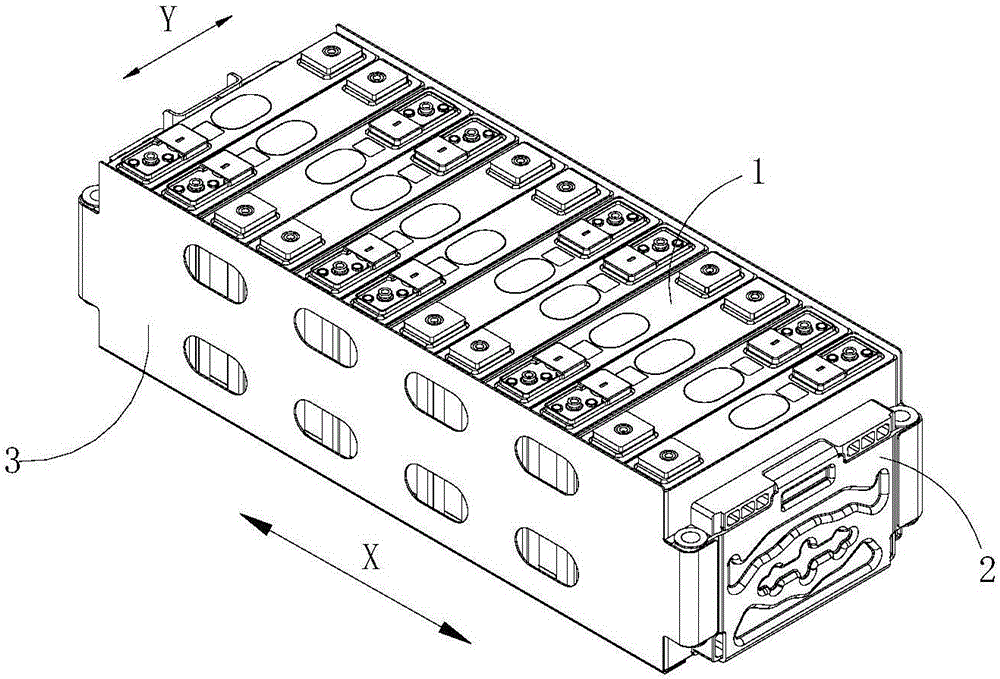
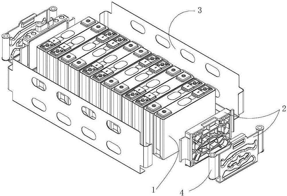
[0047] Such as Figure 1-2 As shown, the embodiment of the present application provides a battery module including a base (not shown in the figure), a plurality of battery units 1, a pair of end plates 2, a pair of side plates 3, and a plurality of sleeve members.

[0048] A plurality of battery cells 1 are located on the base and stacked along the thickness direction of the battery cell 1 according to the requirements of the series and parallel connection of the battery module, and the width faces are closely attached; a pair of end plates 2 are respectively located in the thickness direction of the plurality of battery cells 1 ( figure 1 In the X direction), and adjacent to the outermost battery cell 1 of the plurality of battery cells 1, and along the width direction of the battery cell 1 ( figure 1 In the Y direction) extends; a pair of side p...


PUM


Abstract

The invention relates to a battery module. The battery module comprises a base, end plates, side plates and a plurality of sleeve members, wherein the end plates and the side plates are connected to the base through the sleeve members, each sleeve member comprises a tube body and a connecting piece, and further comprises transition pieces; each transition piece has a transition plane, the transition plane is perpendicular to the axis of the tube body; a fitting surface is disposed on one side of the connecting piece facing the transition piece; the fitting surface is fitted with the transition plane. According to the battery module, the connecting piece can be screwed in the base along the axis of the tube body, connection difficulty between the connecting piece and the base is reduced, and the installation efficiency is improved.

Description

Technical field [0001] This application relates to the field of battery technology, and in particular to a battery module. Background technique [0002] A battery module usually includes a plurality of battery cells, a pair of end plates, a pair of side plates, a base, and a plurality of sleeve members. The pair of end plates and a pair of side plates are connected to each other to form a frame of the battery module. They are arranged side by side in a metal frame. The sleeve component includes a sleeve and a locking bolt. The sleeve is arranged at the corner of the metal frame and is fixedly connected with the end plate or the side plate. The locking bolt passes through the sleeve and extends toward the base, and the head of the locking bolt abuts On the upper end surface of the sleeve, the threaded part of the tail is screwed into the base and the metal frame is fixed on the base. [0003] The sleeve is affected by the processing technology, and the flatness of its upper end su...

Claims


Application Information

Patent Timeline
Patent Type & Authority Applications(China)
IPC IPC(8): H01M2/10H01M50/20H01M50/209H01M50/291
CPCH01M50/291Y02E60/10
Inventor 曹根姚己华张海东陈建利
Owner CONTEMPORARY AMPEREX TECH CO
Learn More