
Card support anti-stay structure and mobile phone

A card tray, fool-proof technology, applied in the direction of telephone structure, telephone communication, electrical components, etc., can solve the problems of reverse insertion of the card tray, damage to the card tray and the card slot, and the card tray is not fool-proof, etc. The effect of convenience and low product cost

Inactive Publication Date: 2017-01-04
GREE ELECTRIC APPLIANCES INC
View PDF3 Cites 1 Cited by
  • Summary
  • Abstract
  • Description
  • Claims
  • Application Information

AI Technical Summary

Problems solved by technology

[0003] The card trays of existing mobile phones are basically not fool-proof, which makes the card trays easy to be inserted backwards in the installation port, which in turn causes damage to the card trays and card slots

Method used


Image

  • Card support anti-stay structure and mobile phone
  • Card support anti-stay structure and mobile phone
  • Card support anti-stay structure and mobile phone

Examples


Embodiment 1

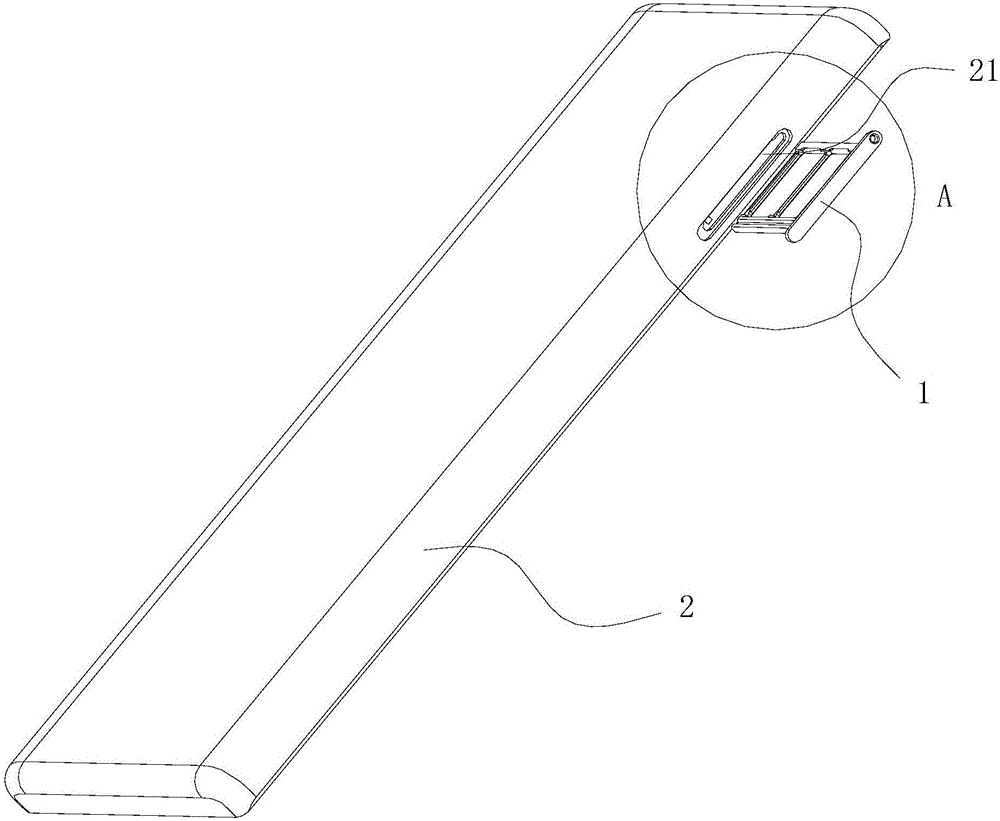
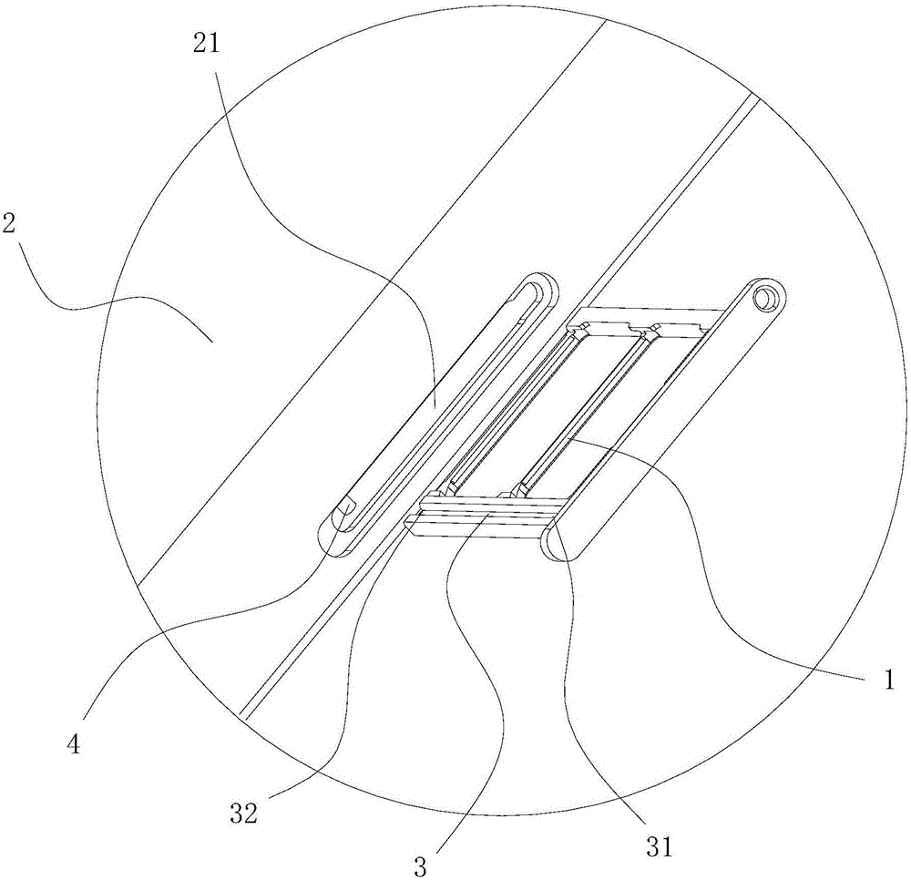
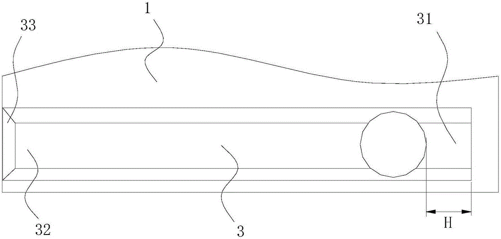
[0029] The preferred embodiment discloses a card support fool-proof structure. like figure 1 and figure 2 As shown, the card holder fool-proof structure includes a card holder 1 and a housing 2, and the housing 2 is provided with a card holder installation port 21, and the card holder 1 can slide in and out of the card holder installation port 21. A groove 3 is provided on the front or back, and a boss 4 matching the groove 3 is provided on the side wall or inner wall of the card tray installation opening 21; or, as Figure 4 As shown, a groove 3 is provided on one side of the card tray 1, and a boss 4 matching the groove 3 is provided on the side wall or inner wall of the card tray installation opening 21; or, as Figure 5 As shown, a boss 4 is provided on the front, back or one side of the card tray 1, and a groove 3 that is compatible with the boss 4 is provided on the inner wall of the card tray installation opening 21, because the groove 3 is arranged on the card holde...

Embodiment 2

[0038] This preferred embodiment discloses a mobile phone, which includes the card tray fool-proof structure as described in the first preferred embodiment. Wherein, the card tray is a tray for carrying the SIM card, and the casing is the back casing of the mobile phone. When it is necessary to install the SIM card, align the boss with the groove, and push the card tray carrying the SIM card into the card tray installation opening to ensure that the card tray will not be installed backwards, and the SIM card will not be damaged due to the card tray installation. Physical damage to the card slot inside the rear case.


PUM


Abstract

The invention discloses a card support anti-stay structure and a mobile phone, and belongs to the technical field of mobile phones and accessories thereof. The card support anti-stay structure is designed for solving the problem that the existing device does not have anti-stay property, etc. The card support anti-stay structure disclosed by the invention comprises a card support and a shell, a card support installation opening is formed in the shell, the card support can slide in and slide out from the card support installation opening a groove is formed in a front face, a back face or a side face of the card support, and a convex column adapted to the groove is arranged on a side wall or an inner wall of the card support installation opening; or, the convex column is arranged on the front face, the back face or the side face of the card support, and a groove adapted to the convex column is formed in the side wall or the inner wall of the card support installation opening; and at least one end of the groove can open for accommodating the slide in and slide out of the convex column. The mobile phone disclosed by the invention comprises the card support anti-stay structure. According to the card support anti-stay structure and the mobile phone disclosed by the invention, the anti-stay is realized by the cooperation of the groove and the convex column, meanwhile a locating function is also provided to prevent a card loaded on the card support from being damaged by the reversely installed card support, the use is convenient, and the product cost is low.

Description

technical field [0001] The invention relates to the technical field of mobile phones and accessories thereof, in particular to a card holder fool-proof structure and a mobile phone including the card holder fool-proof structure. Background technique [0002] When the mobile phone is in use, card structures such as SIM cards need to be installed. These card structures usually need to be carried on the card tray, and slide into and out of the installation opening of the card slot on the housing together with the tray. [0003] The card trays of existing mobile phones are basically not fool-proof, which makes it easy for the card trays to be inserted backwards in the installation opening, thereby causing damage to the card trays and card slots. Contents of the invention [0004] An object of the present invention is to provide a card holder fool-proof structure that is easy to use. [0005] Another object of the present invention is to provide a mobile phone with fool-proof ...

Claims


Application Information

Patent Timeline
IPC IPC(8): H04M1/02
CPCH04M1/026
Inventor 邵龙飞陈长阔龙世才郑亚东许超叶启璐
Owner GREE ELECTRIC APPLIANCES INC
Learn More