A steel pipe discharge rack

A steel pipe and frame technology, applied in the field of steel pipe discharge racks, can solve the problems of low discharge efficiency and high labor intensity of steel pipes, improve discharge efficiency and quality, reduce labor intensity, and prevent scratches and wear Effect

Active Publication Date: 2018-06-22
浙江义腾特种钢管有限公司
View PDF6 Cites 0 Cited by
  • Summary
  • Abstract
  • Description
  • Claims
  • Application Information

AI Technical Summary

Problems solved by technology

[0004] The purpose of the present invention is to overcome the deficiencies of the above-mentioned prior art, and provide a steel pipe discharge rack, which aims to solve the technical problems of low steel pipe discharge efficiency and high labor intensity in the prior art

Method used


Image

  • A steel pipe discharge rack
  • A steel pipe discharge rack

Examples


Embodiment Construction

[0019] In order to make the object, technical solution and advantages of the present invention clearer, the present invention will be further described in detail below through the accompanying drawings and embodiments. However, it should be understood that the specific embodiments described here are only used to explain the present invention, and are not intended to limit the scope of the present invention. Also, in the following description, descriptions of well-known structures and techniques are omitted to avoid unnecessarily obscuring the concept of the present invention.

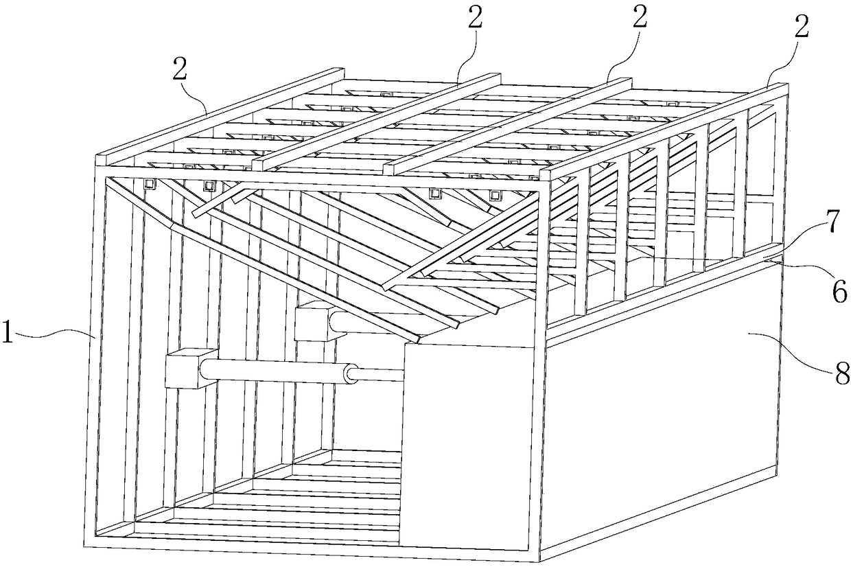
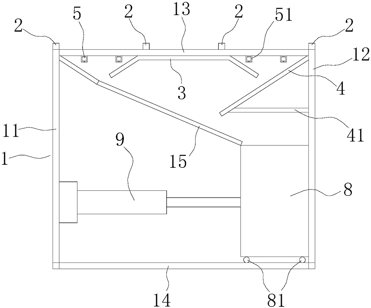
[0020] refer to figure 1 with figure 2 , the embodiment of the present invention provides a steel pipe discharge frame, which is composed of several sub-supports 1, the plurality of sub-supports 1 have the same structure, and are arranged at equal intervals along the same horizontal direction on the same horizontal plane. The upper end surfaces of several sub-supports 1 are connected by several reinf...


PUM


Abstract

The invention discloses a steel tube discharging machine frame. The steel tube discharging machine frame is composed of a plurality of branch supports. The branch supports are identical in structure and are arranged at equal intervals on the same horizontal plane in the same horizontal direction. The upper end faces of the branch supports are connected through a plurality of reinforcing connecting rods to form an integrated frame structure. Each branch support is composed of a back stand rod, a front stand rod, an upper supporting rod, a lower supporting rod and a diagonal rod. Each branch support is provided with an upper buffer plate, a lower buffer plate and a plurality of spreading devices. The upper buffer plates, the lower buffer plates and the spreading devices of the branch supports are located at the corresponding identical positions. Each spreading device is composed of two semicircular or semi-rectangular PPR pipes. The lower ends of the front stand rods of the branch supports are connected into a whole through reinforcing rods. A steel tube chute channel is formed between the reinforcing rods and the lower supporting rods of the branch supports. The bottoms of the branch supports are provided with a steel tube chute. The steel tube discharging machine frame is reasonable in design, achieves automatic discharging, greatly lowers the labor intensity and improves the discharging efficiency and the discharging quality of blank tubes.

Description

【Technical field】 [0001] The invention relates to the technical field of steel pipe rolling mills, in particular to a steel pipe discharging frame. 【Background technique】 [0002] With the development of the iron and steel industry, technology is also constantly developing, which provides a guarantee for the sound and rapid development of my country's iron and steel industry and promotes rapid economic growth. With the continuous improvement of my country's economic level, my country's demand for steel will become larger and larger, and the steady development of the steel industry is the basis for improving my country's economic development level. [0003] At present, the discharge efficiency of steel pipes from the main machine is low, and manual assistance is required to discharge the materials, and then enter the next process, the labor intensity is high, and the degree of automation is low. In order to solve the above problems, the production of steel pipes should be imp...

Claims


Application Information

Patent Timeline
Patent Type & Authority Patents(China)
IPC IPC(8): B21B39/02
CPCB21B39/02
Inventor 朱则军
Owner 浙江义腾特种钢管有限公司
Why Eureka
Try Eureka