
Secondary battery and battery module

A secondary battery and electrode assembly technology, which is applied in the field of secondary batteries and battery modules, can solve problems such as poor air flow and battery explosion, and achieve the effects of improving safety, preventing explosion, and solving battery overcharge problems

Active Publication Date: 2019-10-29
CONTEMPORARY AMPEREX TECH CO
View PDF4 Cites 2 Cited by
  • Summary
  • Abstract
  • Description
  • Claims
  • Application Information

AI Technical Summary

Problems solved by technology

[0003] However, an explosion-proof valve is usually connected to the top cover, and the part of the current cut-off structure located outside the top cover will affect the air flow of the explosion-proof valve. When the secondary battery generates internal gas due to an accidental internal short circuit, the air flow is not smooth. May cause the battery to explode, resulting in a serious accident

Method used

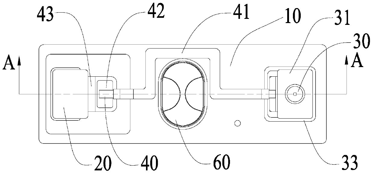
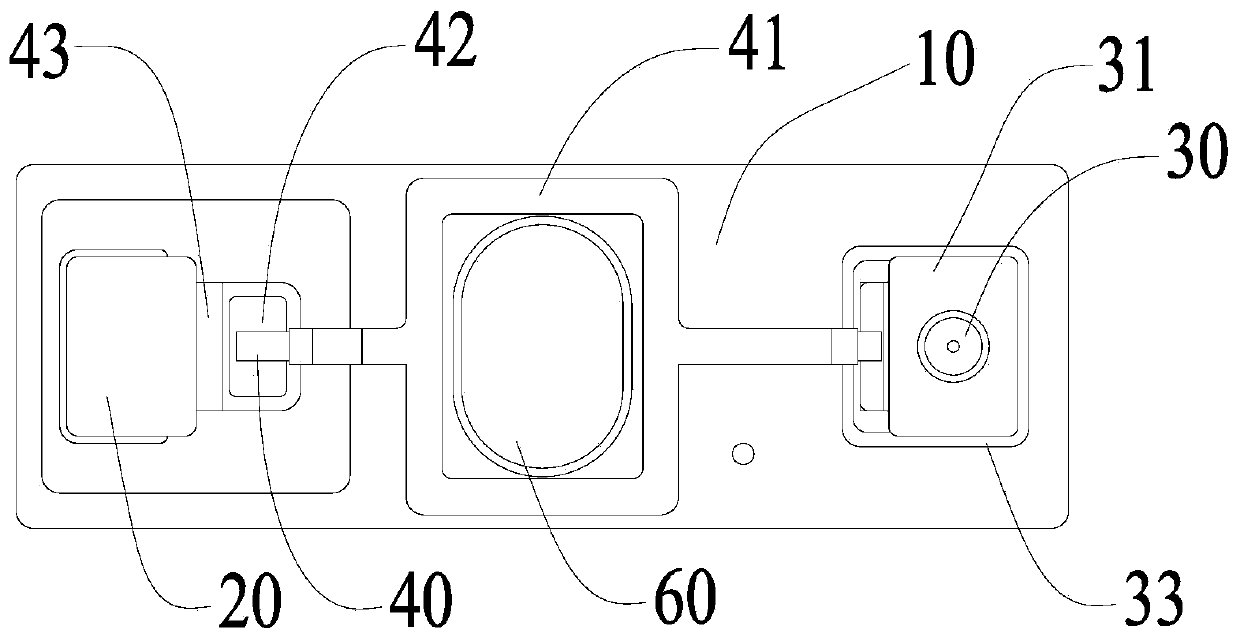
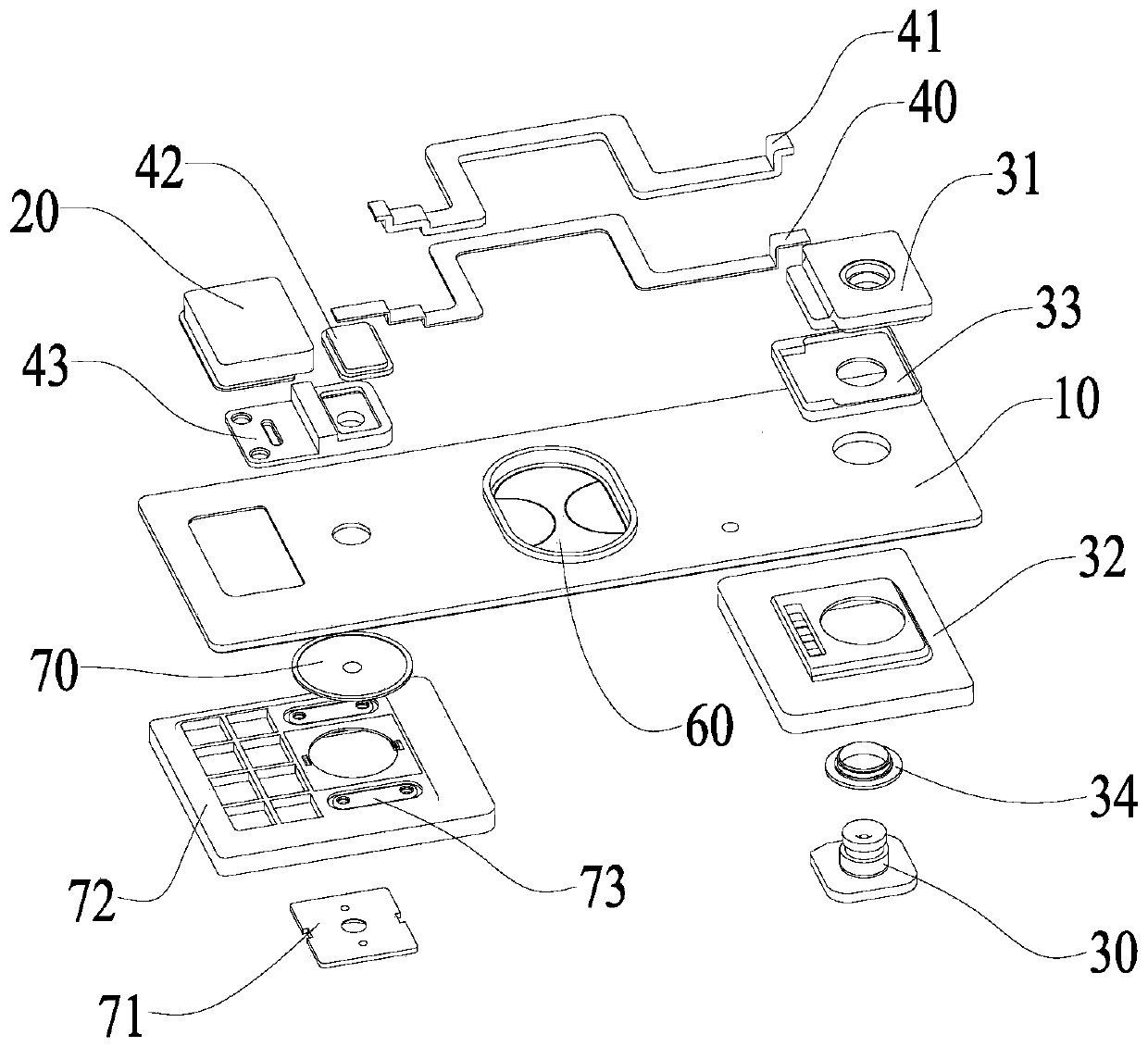

Image

  • Secondary battery and battery module
  • Secondary battery and battery module
  • Secondary battery and battery module

Examples


no. 1 example

[0115] In the first embodiment, the flipping piece 70 is connected to the top cover piece 10, and the first terminal 20 is electrically connected to the top cover piece 10, specifically, as Figure 1-3 , 4, and 7, the top cover sheet 10 is provided with a first through hole, and the flip sheet 70 is attached to the top cover sheet 10 and seals the first through hole, so that the top cover sheet 10, the flip sheet 70 and the housing form a seal cavity. The first terminal 20 is electrically connected to the top cover sheet 10 , preferably the top cover sheet 10 may be provided with a fourth groove, and the first terminal 20 is inserted into the fourth groove; the second terminal 30 is electrically insulated from the top cover sheet 10 . The connecting piece 40 is electrically insulated from the top cover sheet 10 , and at least a part of the connecting piece 40 (the contact portion 401 when the contact portion 401 is provided) is opposite to the first through hole. In the norma...

no. 2 example

[0116] In the second embodiment, the turning piece 70 is attached to the first terminal 20, such as Figure 3a , 4a As shown, a first through hole is provided on the first terminal 20, and the flipping piece 70 seals the first through hole. At this time, when the connecting piece 40 is located on the side of the top cover sheet 10 away from the first pole piece, the top cover sheet 10 is provided with a second through hole, and the second through hole is opposite to the first through hole. In the normal state, the first pole piece is electrically connected to the first terminal 20 through the reversing piece 70; In the connected state, the flipped flip 70 is electrically connected to the connector 40 , so that the first terminal 20 is electrically connected to the second terminal 30 through the flip 70 , the connector 40 . When the secondary battery expands or compresses and when the top cover sheet 10 is welded to the housing, the resulting force will be applied to the top ...


PUM


Abstract

The present application relates to the technical field of production of energy storage devices, in particular to a secondary battery and a battery module. At least one of the first terminal and the second terminal is electrically insulated from the top cover; the connector is electrically connected to the second terminal; the explosion-proof valve is installed on the top cover, and the connector is located outside the projection range of the explosion-proof valve along the height direction , and is located within the projection range of the top cover sheet along the height direction. In normal state, the first pole piece is electrically connected to the first terminal through the turning piece, and the second pole piece is electrically connected to the second terminal; when the pressure in the secondary battery exceeds the reference pressure, the turning piece can be turned over so that the turning piece is disconnected from the second terminal. The electrical connection state of one pole piece, and the turned overturned piece is electrically connected with the contact part, so that the first terminal and the second terminal are electrically connected. Even if the car is in the running state, the application will not turn off suddenly, which improves the safety of the car sex.

Description

technical field [0001] The present application relates to the technical field of production of energy storage devices, in particular to a secondary battery and a battery module. Background technique [0002] For EV hard-shell batteries, in order to solve the overcharge problem, the industry generally adopts a solution to cut off the main circuit of the battery before the battery fails to prevent the battery from continuing to charge to ensure battery safety. The usual structure is: a current cut-off structure is set in the main circuit where the first terminal is electrically connected to the electrode assembly, and the second terminal is always electrically insulated from the current cut-off structure. When the battery is overcharged, internal gas is generated, and the internal air pressure increases to a certain level. When the value is high, the current cut-off structure is activated to disconnect the circuit between the first terminal and the electrode assembly, preventi...

Claims


Application Information

Patent Timeline
Patent Type & Authority Patents(China)
IPC IPC(8): H01M2/12H01M10/04H01M50/30
CPCH01M10/04H01M50/30Y02E60/10Y02P70/50
Inventor 李全坤林永寿蔡如来
Owner CONTEMPORARY AMPEREX TECH CO
Learn More