

Automotive sunshield board
A technology for sun visors and vehicles, which is applied to vehicle parts, anti-glare equipment, transportation and packaging, etc. It can solve the problem of scattering of cosmetic mirror parts, achieve the effects of improving the freedom of choice, suppressing scattering, and reducing cost and quality
- Summary
- Abstract
- Description
- Claims
- Application Information
AI Technical Summary
Problems solved by technology
Method used
Image

Examples
Embodiment 1
[0054] (1) Structure of vehicle sun visor
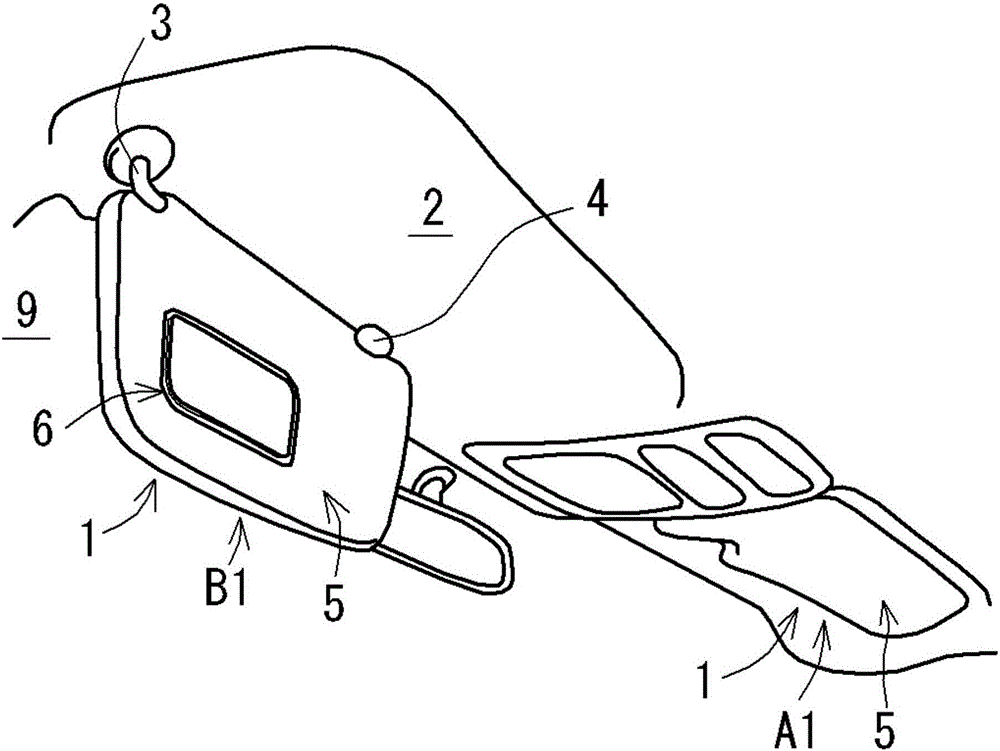
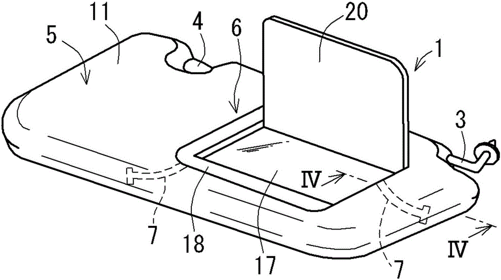
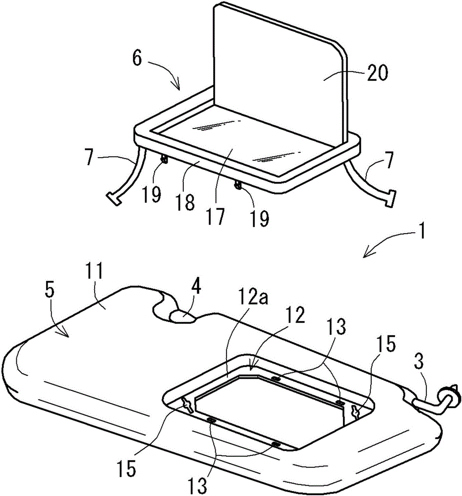
[0055] like Figure 1 ~ Figure 3 As shown, the vehicle sun visor 1 of this embodiment includes a sun visor main body 5 supported on the vehicle roof 2 via a support arm 3 and a vanity mirror member 6 attached to the surface side of the sun visor main body 5 . The vehicle sun visor 1 includes a connecting member 7 (also referred to as a "tether"). The connecting member 7 is in the shape of a belt, and when the vanity mirror member 6 falls off from the sun visor main body 5, it connects the sun visor main body 5 and the vanity. The mirror member 6 is connected so as to maintain a predetermined separated state.
[0056] like figure 1 As shown, the sun visor main body 5 is formed in a substantially rectangular shape in plan view. A bearing portion (not shown) that rotatably supports one end side of the substantially L-shaped support arm 3 is attached to an upper corner portion of the sun visor main body 5 . The other end side of the...
Embodiment 2
[0070] Next, the vehicle sun visor of the second embodiment will be described. In addition, in the vehicle sun visor of the second embodiment, substantially the same components as those of the vehicle sun visor 1 of the first embodiment are given the same reference numerals, and detailed description thereof will be omitted.
[0071] (1) Structure of vehicle sun visor
[0072] like Figure 8A , 8B As shown, the vehicle sun visor 31 of this embodiment includes a sun visor main body 5 supported by the vehicle roof 2 via a support arm 3 and a vanity mirror member 6 attached to the surface side of the sun visor main body 5 . This vehicle sun visor 31 includes a belt-shaped first connecting member 32 and a belt-shaped second connecting member 33 (also referred to as a "tether"). The first connecting member 32 and the second connecting member 33 connects the sun visor main body 5 and the vanity mirror member 6 to maintain a predetermined separated state when the vanity mirror memb...
Embodiment 3
[0079] Next, the sun visor for a vehicle according to the third embodiment will be described. In addition, in the vehicle sun visor of the third embodiment, the same reference numerals are attached to the components substantially the same as those of the vehicle sun visor 1 of the above-mentioned first embodiment, and detailed description thereof will be omitted.
[0080] (1) Structure of vehicle sun visor
[0081] like Figure 11 and Figure 12 As shown, the vehicle sun visor 41 of this embodiment includes a sun visor main body 5 supported by the vehicle roof 2 via a support arm 3 and a vanity mirror member 6 mounted on the surface side of the sun visor main body 5 . This vehicle sun visor 41 includes a connecting member 42 (also referred to as a "tether"). The connecting member 42 is in the shape of a belt, and when the vanity mirror member 6 is detached from the sun visor main body 5, the sun visor main body 5 and the vanity are connected together. The mirror member 6 is...
PUM
 Abstract
Description
Claims
Application Information