A new type of continuously variable speed energy-saving booster governor for motorcycles

A technology of continuously variable transmission and motorcycles, which is applied to vehicle gearboxes, vehicle components, chain/belt transmissions, etc., and can solve problems such as unsmooth belts and out-of-sync speed reduction

Active Publication Date: 2021-12-14
夏婷
View PDF5 Cites 0 Cited by
  • Summary
  • Abstract
  • Description
  • Claims
  • Application Information

AI Technical Summary

Problems solved by technology

[0005] Aiming at the problems existing in the prior art that the deceleration of the driving wheel and the deceleration of the braking system are not synchronized, and the belt is not smooth during operation, the present invention provides a new type of continuously variable speed energy-saving booster governor for motorcycles, the purpose of which is to realize The synchronous deceleration of the driving wheel and the deceleration of the braking system ensures convenient operation during driving without potential safety hazards, prevents the problem of unsmooth rotation of the pulley during driving, and ensures smooth operation of the motorcycle

Method used


Image

  • A new type of continuously variable speed energy-saving booster governor for motorcycles
  • A new type of continuously variable speed energy-saving booster governor for motorcycles
  • A new type of continuously variable speed energy-saving booster governor for motorcycles

Examples


Embodiment 1

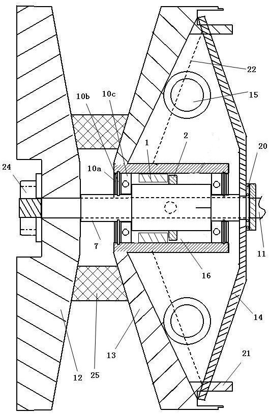
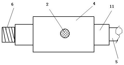
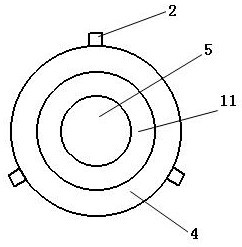
[0033] figure 2 It is a schematic diagram of the side structure diagram of the main shaft 11. image 3 yes figure 2 Schematic diagram of the right-view structure of the central axis 11. In this embodiment, three protruding pins are arranged on the outer periphery of the middle part 4 of the outer periphery of the main shaft 11, and the three protruding pins 2 are evenly arranged on the middle part 4 of the outer periphery of the main shaft 11. The angles between the three protruding pins 2 are 120°, when the main shaft 11 rotates, the three convex pins provided on the middle part 4 of the outer circumference of the main shaft 11 pass through the concave teeth of the three curved triangular teeth arranged on the inner circumference of the conical moving wheel 13 set on the outer circumference of the main shaft.

[0034] In the above-mentioned new motorcycle continuously variable speed energy-saving booster governor, the heights of the three protruding pins 2 are less than o...

Embodiment 2

[0040] Figure 4 It is a schematic diagram of the side structure of the sleeve arranged outside the main shaft 11. The graph is in figure 1 As a further improvement on the basis of the above, in this embodiment, three protruding pins 2 are arranged on the outer periphery of the middle part 4 of the outer periphery of the sleeve 7, and the three protruding pins 2 are equally arranged on the middle part 4 of the outer periphery of the sleeve 7. The angle between them is 120°. When the sleeve 7 rotates, the three convex pins 2 provided on the middle part 4 of the outer periphery of the sleeve 7 pass through the concave teeth of the three curved triangular teeth.

[0041] In the above-mentioned new motorcycle continuously variable speed energy-saving booster governor, the outer periphery of the main shaft 11 is provided with a sleeve 7, one end of the sleeve 7 is located on the outer conical surface of the tapered fixed wheel 12, and the main shaft 11 is fixedly connected with t...


PUM


Abstract

A new type of continuously variable speed energy-saving booster governor for motorcycles, which belongs to the field of motorcycle parts. A plurality of curved shapes are evenly arranged on one of the middle part of the inner circumference of the central hole of the conical moving wheel or the middle part of the outer circumference of the main shaft. For triangular teeth, correspondingly, a plurality of protruding pins with equal numbers and matching each other are arranged on one of the middle part of the outer circumference of the main shaft or the middle part of the inner circumference of the central hole of the conical moving wheel. Internally, the governor with this structure can not only accelerate forward in a short period of time, but also decelerate in a short period of time, so that the deceleration of the active wheel is synchronized with the deceleration speed of the braking system, eliminating the need for There are potential safety hazards in the technology, and at the same time, it can save fuel consumption and reduce travel costs, so that drivers can operate the vehicle with ease on the basis of safety.

Description

technical field [0001] The invention relates to a speed governor, in particular to a novel motorcycle stepless variable speed energy-saving booster speed governor, which belongs to the field of motorcycle parts. Background technique [0002] The current motorcycle technology is relatively mature, but any technology is not the best, only better. On the basis of safety, fuel saving and driving convenience are the relentless pursuit of motorcycle researchers. The research is constantly innovating, and the structural innovation of the speed governor makes the motorcycle reach the fuel-saving effect. In the energy-saving driving wheel structure of the continuously variable transmission motorcycle with the patent application number 201210322273.9, such a technology is disclosed. Figure 6 It is a structural schematic diagram of the prior art solution, Figure 7 yes Figure 6 Schematic diagram of the central axis, Figure 8 yes Figure 6 Middle A / A cross-sectional schematic diagr...

Claims


Application Information

Patent Timeline
Patent Type & Authority Patents(China)
IPC IPC(8): B62M9/08
CPCB62M9/08
Inventor 胡福喜焦红军
Owner 夏婷
Why Eureka
Try Eureka