Method for stabilizing the friction coefficient gradient of a clutch in a motor vehicle

A technology of motor vehicle and friction coefficient, applied in the direction of clutch, mechanical equipment, etc., can solve the problem of increased vibration tendency of motor vehicle, and achieve the effect of high speed

Active Publication Date: 2017-10-24
SCHAEFFLER TECH AG & CO KG
View PDF2 Cites 0 Cited by
  • Summary
  • Abstract
  • Description
  • Claims
  • Application Information

AI Technical Summary

Problems solved by technology

Of course, when using such a pull control device, there is the risk that the phase shift and thus the tendency of the motor vehicle to vibrate will be further intensified

Method used


Image

  • Method for stabilizing the friction coefficient gradient of a clutch in a motor vehicle

Examples


Embodiment Construction

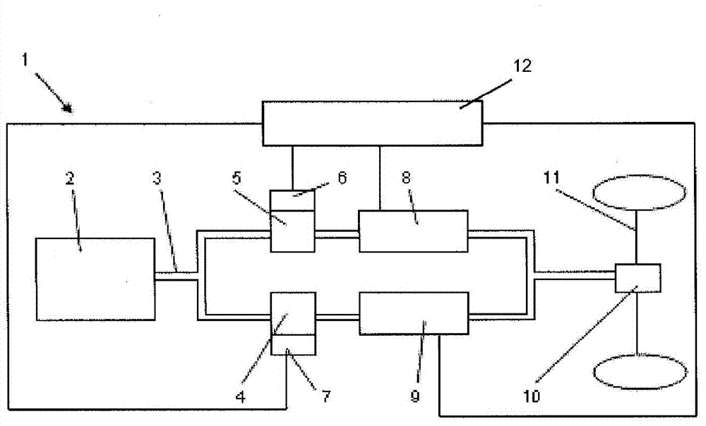
[0018] figure 1 A schematic diagram of a drive train 1 of a motor vehicle with a dual clutch transmission is shown. In this case, a drive unit 2 , for example an internal combustion engine, is connected via a shaft 3 to a dual clutch transmission, which is described in detail below.

[0019] A dual clutch transmission consists of two subsystems. The first sub-train here has a first sub-transmission clutch 4 , which leads to a first sub-drive train 9 . Drive unit 2 in the form of an internal combustion engine is also connected to a second sub-train, which includes a second sub-transmission clutch 5 , which leads to a second sub-drive train 8 . The two drive train sub-trains 8 , 9 are led via an axle differential 10 to a transaxle 11 of the motor vehicle.

[0020] The different gears are separated in the sub-drive trains 8 , 9 . Thus, the first power train sub 9 has odd gears, eg 1, 3, 5, while the second power train sub 8 has even gears, eg 2, 4, 6. When changing from one ...


PUM


Abstract

The invention relates to a method for stabilizing a coefficient of friction gradient of a clutch in a motor vehicle, in which a drive train can be connected to an internal combustion engine by means of a clutch, and a torque is transmitted to an output, the drive train having an engaged gear. In a method that guarantees an almost constant positive coefficient of friction gradient, the clutch slips briefly when the motor vehicle travels in a low load range.

Description

technical field [0001] The invention relates to a method for stabilizing the friction coefficient gradient of a clutch in a motor vehicle, wherein a drive train can be connected to an internal combustion engine by means of the clutch and transmit torque to an output device, wherein the drive train has an engaged gear . Background technique [0002] Shifting and starting clutches used in motor vehicles are generally capable of varying coefficients of friction over their operating time. It is desirable that the coefficient of friction gradient remain approximately positive over the life of the clutch. If a negative coefficient of friction gradient occurs via the slip speed, frictional vibrations can occur in the vehicle, which significantly impairs driving comfort. Whether a negative coefficient of friction gradient occurs depends very much on the driving behavior of the respective driver. A negative coefficient of friction gradient occurs when the clutch is overloaded on t...

Claims


Application Information

Patent Timeline
Patent Type & Authority Patents(China)
IPC IPC(8): F16D48/06
CPCF16D48/06F16D2500/10412F16D2500/1045F16D2500/30806F16D2500/3127F16D2500/31466F16D2500/50221F16D2500/50684F16D2500/5085F16D2500/5122F16D2500/5126F16D2500/525F16D2500/70426F16D2500/70458F16D2500/70488F16D2500/7105
Inventor 安德烈亚斯·格茨延斯·克拉默
Owner SCHAEFFLER TECH AG & CO KG
Why Eureka
Try Eureka