Electric vehicles and electric vehicle supply rails

A technology for electric vehicles and power supply rails, applied in electric vehicles, battery/battery traction, wheels, etc., can solve the problems of restricting the promotion of electric vehicles, charging difficulties, etc., to reduce the consumption of energy storage, improve the cruising range, and optimize the power supply effect of technology

Active Publication Date: 2019-06-04
FAFA AUTOMOBILE (CHINA) CO LTD
View PDF5 Cites 0 Cited by
  • Summary
  • Abstract
  • Description
  • Claims
  • Application Information

AI Technical Summary

Problems solved by technology

In the process of realizing the present invention, the inventor found that the defects of the present invention are: the charging piles in general cities are not popular, and charging is difficult; during the charging process, the electric vehicle needs to be parked at the location of the charging pile, and the electric vehicle cannot continue to drive. The above two defects greatly limit the promotion of electric vehicles

Method used


Image

  • Electric vehicles and electric vehicle supply rails
  • Electric vehicles and electric vehicle supply rails
  • Electric vehicles and electric vehicle supply rails

Examples


Embodiment 1

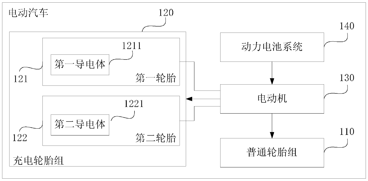
[0033] figure 1 It is a schematic structural diagram of an electric vehicle provided in Embodiment 1 of the present invention. Such as figure 1 As shown, the electric vehicle includes:

[0034] A set of normal tires 110 , a set of rechargeable tires 120 , a motor 130 for driving the set of normal tires 110 , and a power battery system 140 for powering the motor 130 .

[0035] The tire surface of the first tire 121 in the charging tire group 120 is provided with a first conductor 1211, and the tire surface of the second tire 122 in the charging tire group 120 is provided with a second conductor 1221. The tire 121 and the second tire 122 are located on different sides of the electric vehicle.

[0036] The positive pole of the power supply of the motor 130 is connected to the first conductor 1211 , and the negative pole of the power supply of the motor 130 is connected to the second conductor 1221 .

[0037] Wherein, when the electric vehicle is running on the power supply tr...

Embodiment 2

[0062] This embodiment is embodied on the basis of Embodiment 1. In this embodiment, the power supply positive pole of the power battery system is connected to the first tire in the charging tire set, and the power battery system’s The negative pole of the power supply is connected to the second tire in the charging tire group, so that when the electric vehicle is running on the power supply track, the power battery system can be charged through the power supply track.

[0063] Obviously, through the technical solution of Embodiment 1, when the electric vehicle is driving on the power supply track, the electric motor in the electric vehicle can be powered by the power supply track instead of the power battery system.

[0064] In this embodiment, in addition to using the power supply track to supply power to the electric vehicle, the power supply track is further used to charge the power battery system in the electric vehicle. The technical effect of charging is to further impr...

Embodiment 3

[0070] Figure 5 It is a schematic structural diagram of an electric vehicle power supply track provided by Embodiment 3 of the present invention. The electric vehicle power supply rail can be used in conjunction with the electric vehicles provided in Embodiment 1 and Embodiment 2. Such as Figure 5 As shown, the electric vehicle power supply track includes:

[0071] The insulating roadbed 51 and two parallel power supply rails 52 arranged on the insulating roadbed 51 , the two parallel power supply rails 52 have a set height relative to the ordinary road surface.

[0072] Wherein, one of the power supply rails 52 is used to provide a positive power supply, and the other rail is used to provide a negative power supply, so that when the power supply rail and the charging tire set of the electric vehicle described in Embodiment 1 and Embodiment 2 When fully contacted, the electric motor of the electric vehicle is powered.

[0073] Wherein, the height of the power supply rail...


PUM


Abstract

The embodiment of the invention discloses an electric car and an electric car power supply track and relates to the technical field of electric cars. The electric car comprises a common tire set, a rechargeable tire set, an electric motor for driving the common tire set, and a power battery system for providing power for the electric motor. A first electric conductor is arranged on the tire surface of a first tire in the rechargeable tire set. A second electric conductor is arranged on the tire surface of a second tire in the rechargeable tire set. The first tire and the second tire are located on the different sides of the electric car. The positive electrode and the negative electrode of a power supply of the electric motor are connected with the first electric conductor and the second electric conductor correspondingly. When the electric car runs on the power supply track, the power supply track drives the electric motor with power, and when the electric car runs on a common pavement, the power battery system drives the electric motor with power. By means of the technical scheme, the charging technique for existing electric cars is optimized, and the increasing demand of people for efficient and convenient power supply to electric cars is met.

Description

technical field [0001] Embodiments of the present invention relate to electric vehicle technology, and in particular to an electric vehicle and an electric vehicle power supply rail. Background technique [0002] As oil and other fuels run out, people are turning to electric vehicles, which have many advantages. An electric vehicle refers to a vehicle that is powered by a vehicle-mounted power battery and drives the wheels with an electric motor, and meets the requirements of road traffic and safety regulations. [0003] Generally speaking, the power input terminals of the motor in an electric vehicle are electrically connected to the positive and negative electrodes of the power battery respectively, and the power battery provides power for the motor, thereby driving the wheels to rotate. However, limited by the energy of the power battery, the power battery needs to be charged whenever the electric vehicle travels for a certain distance. [0004] The existing way of char...

Claims


Application Information

Patent Timeline
Patent Type & Authority Patents(China)
IPC IPC(8): B60L5/38B60L50/53B60B19/00
CPCB60B19/00B60L5/38B60L50/53Y02T10/70
Inventor 陈祥斌
Owner FAFA AUTOMOBILE (CHINA) CO LTD
Why Eureka
Try Eureka