Rack-driven rotational core pulling device at cover half position of injection mold

An injection mold and rack technology, which is applied in the field of rack-driven rotary core-pulling devices, can solve the problems of many potential failure links, high failure rate, and long maintenance time, so as to reduce failures, overcome high failure rates and reduce costs. Effect

Inactive Publication Date: 2017-02-08
NINGBO YUEFEI MOLD
View PDF6 Cites 6 Cited by
  • Summary
  • Abstract
  • Description
  • Claims
  • Application Information

AI Technical Summary

Problems solved by technology

[0002] The undercut structure located on the inner surface of the injection molded product is called the inner undercut, and the undercut structure located on the outside of the injection molded product is called the outer undercut. Refer to Figure 4 , Figure 5 , for injection molded products with undercuts on both inside and outside sides, in addition to setting a core-pulling mechanism for inner undercuts at the movable mold, the injection mold also needs to set a core-pulling mechanism for outer undercuts at the fixed mold. Core-pulling mechanism: For the core-pulling of the external undercut, the existing technology adopts an oil cylinder at the fixed mold to drive the undercut core-pulling block for core-pulling. Since the drive of the oil cylinder involves many factors such as the quality of the oil cylinder, hydraulic oil circuit, and control circuit, Therefore, there are many potential failure links, high failure rate, frequent maintenance, many man-hours for maintenance, and high overall cost of mold operation. Therefore, the existing technology has the problems and deficiencies of high failure rate and high cost

Method used


Image

  • Rack-driven rotational core pulling device at cover half position of injection mold
  • Rack-driven rotational core pulling device at cover half position of injection mold
  • Rack-driven rotational core pulling device at cover half position of injection mold

Examples


Embodiment Construction

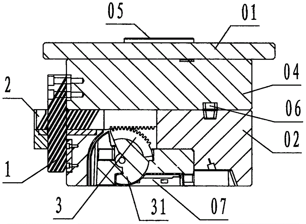
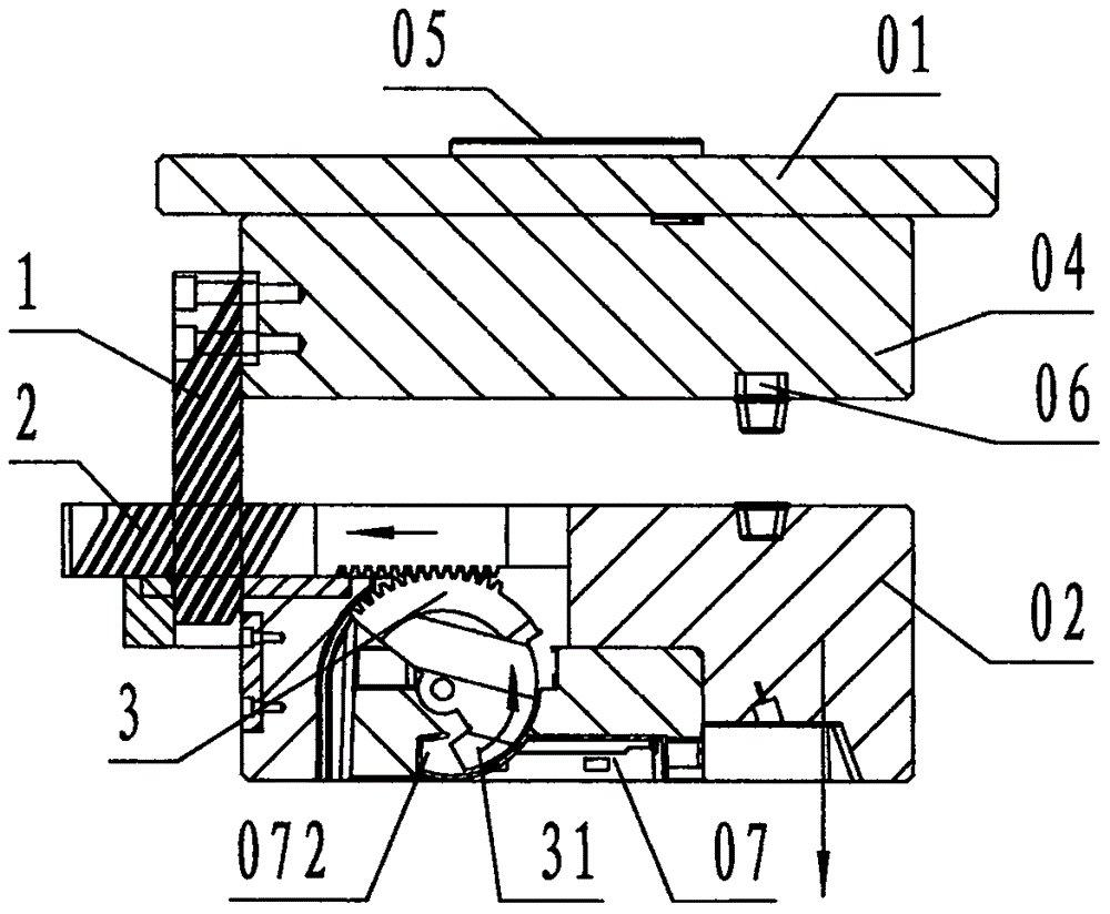
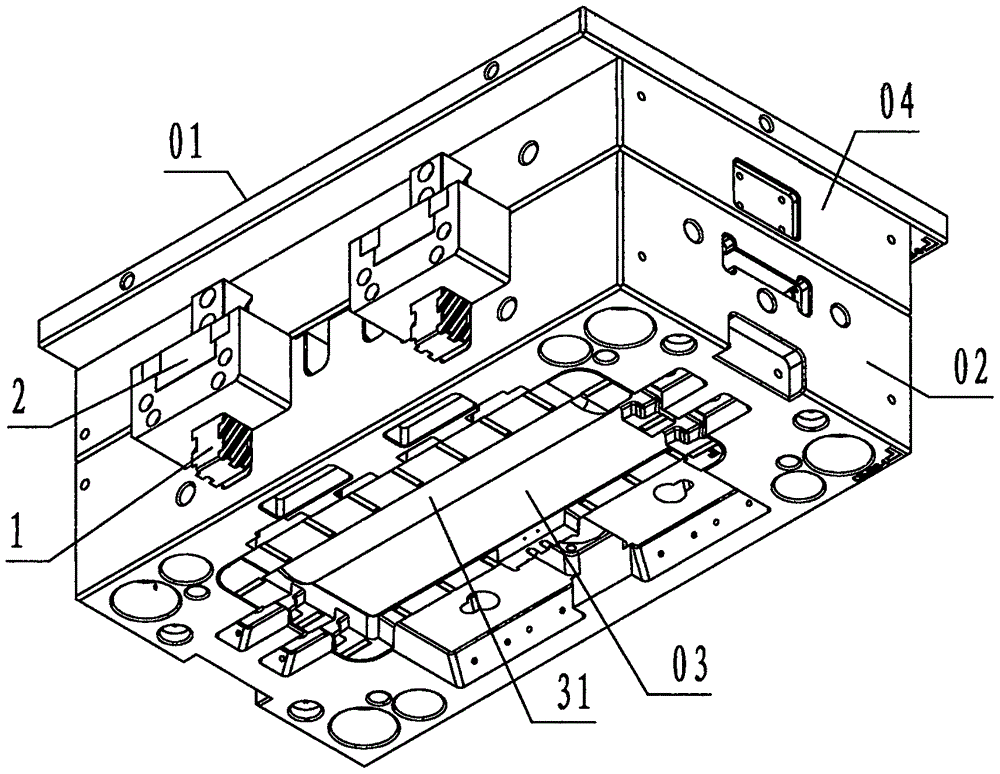
[0020] refer to Figure 1 to Figure 5 , a rack-driven rotary core-pulling device at the fixed part of the injection mold of the present invention includes a longitudinal rack 1, a transverse rack 2, and an arc gear 3, wherein: the longitudinal rack 1 is rectangular As a steel member, the front and rear sides of the longitudinal rack 1 are provided with helical teeth inclined upward from left to right, spaced from each other, and trapezoidal in cross section;

[0021] The transverse rack 2 is a rectangular strip-shaped steel member, and the left part of the transverse rack 2 is provided with a rectangular through hole in the up and down direction, which is called a tooth hole. The helical teeth of 1 correspond to the matching helical grooves; the lower part of the right part of the transverse rack 2 is provided with straight teeth spaced from each other and having a trapezoidal cross-section;

[0022] The arc gear 3 is a steel member in the shape of a fan ring block, and the o...


PUM


Abstract

The invention discloses a rack-driven rotational core pulling device at the cover half position of an injection mold. The rack-driven rotational core pulling device comprises a longitudinal rack (1), a transverse rack (2) and a circular arc gear (3). According to the adopted technical scheme, the longitudinal rack is located on the outer side face of a cover half carrier plate in the up-down direction, the upper end of the longitudinal rack is fixedly connected with the outer side face of the cover half carrier plate, the transverse rack is located in a sliding groove formed in a cavity plate in the left-right direction, the circular arc gear is rotationally located in the cavity plate, the longitudinal rack is engaged with the transverse rack, the transverse rack is engaged with the circular arc gear, and the circular arc gear is connected with an inverted buckle core pulling block; and when the rack-driven rotational core pulling device works, the longitudinal rack drives the transverse rack to be pulled out leftwards, the transverse rack drives the circular arc gear and the inverted buckle core pulling block to rotate in the anticlockwise direction, and the inverted buckle core pulling block is rotated to complete core pulling from an outer inverted buckle. By means of mechanical drive, injection mold outer inverted buckle core pulling achieves the purposes that faults are reduced and the cost is reduced.

Description

technical field [0001] The invention relates to a core-pulling and demoulding device, specifically a rack-driven rotary core-pulling device installed on the fixed mold side of an injection mold for core-pulling the outer undercut of a product. . Background technique [0002] The undercut structure located on the inner surface of the injection molded product is called the inner undercut, and the undercut structure located on the outside of the injection molded product is called the outer undercut. Refer to Figure 4 , Figure 5 , for injection molded products with undercuts on both inside and outside sides, in addition to setting a core-pulling mechanism for inner undercuts at the movable mold, the injection mold also needs to set a core-pulling mechanism for outer undercuts at the fixed mold. Core-pulling mechanism: For the core-pulling of the external undercut, the existing technology adopts an oil cylinder at the fixed mold to drive the undercut core-pulling block for cor...

Claims


Application Information

Patent Timeline
Patent Type & Authority Applications(China)
IPC IPC(8): B29C45/33
CPCB29C45/332
Inventor 冯宗法赵望林宗泽潘功良杨敏
Owner NINGBO YUEFEI MOLD
Why Eureka
Try Eureka