Liquid medium separation device

A separation device and liquid medium technology, applied in the direction of filtration separation, separation method, mobile filter element filter, etc., can solve the problems of complex manufacturing process, high failure rate and high installation accuracy requirements, and achieve the effect of overcoming complex manufacturing process.

Inactive Publication Date: 2012-12-05
魏家全
View PDF0 Cites 0 Cited by
  • Summary
  • Abstract
  • Description
  • Claims
  • Application Information

AI Technical Summary

Problems solved by technology

[0003] The purpose of the present invention is to provide a liquid medium separation device, which overcomes the complex manufacturing process, high installation accuracy requirements, easy blockage of screen holes or screen slots, low separation efficiency and failure rate existing in existing centrifugal screens and rotor screens. Defects that are taller, less effective at separating particles or fibers of different specific gravity

Method used


Image

  • Liquid medium separation device

Examples


Embodiment Construction

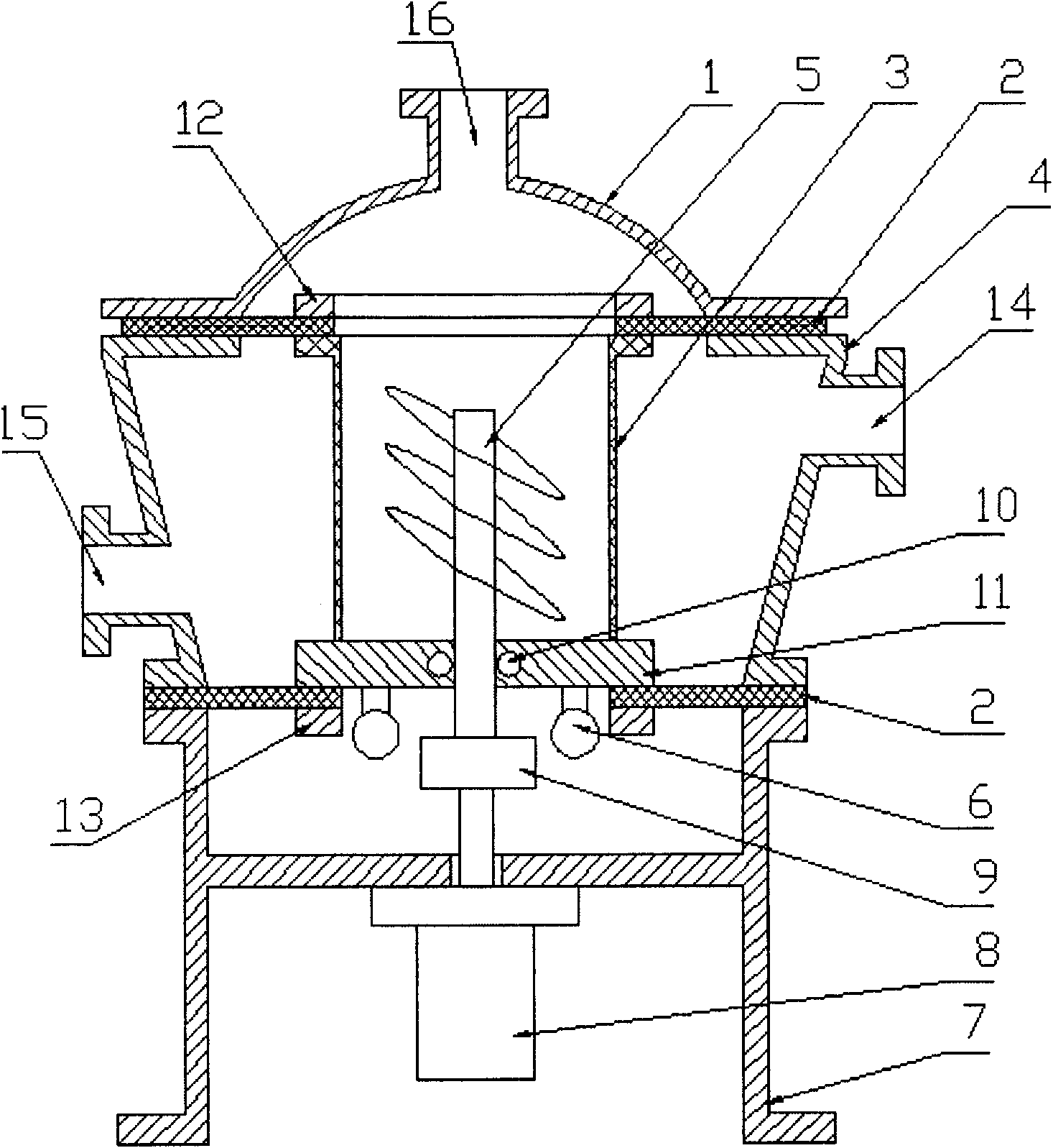
[0010] The separation device has a cylindrical screen 3, and the cylindrical screen 3 is installed on the circular supporting plate 11, and the upper flange 12 and the lower flange 13 respectively install two elastic diaphragms 2 on the circular supporting plate 11. The bottom surface of the bottom surface and the upper mouth of the cylindrical screen 3, the spiral impeller shaft 5 is installed in the center of the cylindrical screen 3 through the circular support plate 11 and the upper flange 12, and the mechanical high-frequency vibration device 6 Installed at the bottom of the circular support plate 11, the above-mentioned components are installed in the center of the shell through the elastic diaphragm 2 above and below the cylindrical screen 3, and installed on the top of the base 7, and the motor 8 is installed and fixed at the center of the bottom of the base 7 On the shaft, the flexible coupling 9 is connected to the screw shaft 5 , and the upper cover 1 is fixed to the...


PUM


Abstract

A liquid medium separation device has a cylindrical sieve mesh mounted on a round support plate, two elastic membranes are mounted at the bottom of the round support plate and the upper opening part of the cylindrical sieve mesh by an upper and a lower flange respectively, a spiral blade shaft is mounted at the central part of the cylindrical sieve mesh via the round support plate and the upper flange, a mechanical high-frequency vibration exciting device is mounted at the bottom of the round support plate, the abovementioned parts are mounted in the central part of a housing via the elastic membranes at the upper and lower parts of the cylindrical sieve mesh and mounted above a base, a motor is mounted and fixed on a central shaft at the bottom of the base, a flexible shaft coupling is connected with the spiral blade shaft, and an upper cover is mounted and fixed to the upper opening part of the housing.

Description

technical field [0001] The invention relates to a separation device, in particular to a liquid medium separation device, and belongs to the technical field of liquid medium separation equipment. Background technique [0002] In papermaking, food, pharmaceutical, chemical and other corresponding fields, it is often necessary to separate particles or fibers with different sizes, shapes and specific gravity from the liquid medium. At present, the main equipment to achieve the separation of the above liquid medium is the centrifuge Screen and rotor screen, because centrifugal screen and rotor screen are a cylindrical screen drum installed in a circular shell, the surface of the screen drum has screen holes or screen slots, and the rotor is installed in the screen drum or near the surface of the screen drum Several rotors are installed, and the slurry entering the screen drum passes through the screen holes or slots under the action of the centrifugal force generated by the rotat...

Claims


Application Information

Patent Timeline
Patent Type & Authority Applications(China)
IPC IPC(8): B01D33/03B01D33/80
Inventor 魏家全
Owner 魏家全
Why Eureka
Try Eureka