Draw gear assembly and rail vehicle with draw gear assembly

A rail vehicle and coupler technology, applied in the field of rail vehicles, can solve problems such as damage to upper equipment, increase the risk of derailment, and inability to fully absorb energy, so as to achieve the effect of improving passive safety

Active Publication Date: 2017-02-08
CRRC QINGDAO SIFANG CO LTD
View PDF7 Cites 14 Cited by
  • Summary
  • Abstract
  • Description
  • Claims
  • Application Information

AI Technical Summary

Problems solved by technology

[0003] At present, in order to reduce the air resistance and improve the starting performance of the train, the head of the train usually adopts a streamlined tip shuttle design; although this design reduces the running resistance of the train and increases the speed of the train, the space at the front end of the train is narrow and can only accommodate In the lower coupler part, it is no longer possible to arrange a large energy-absorbing mechanism
[0004] When two high-speed trains collide, the coupler is the first to be impacted. Although the coupler can be set as an energy-absorbing coupler, its energy absorption is limited and cannot completely absorb the energy generated by the collision of the train. During the process, the hidden danger of intruding into the upper part of the guide part and damaging the upper equipment, or falling onto the track increases the risk of derailment
[0005] Therefore, how to improve the existing coupler structure to fully ensure the function of the energy-absorbing module at the rear end of the coupler, and to avoid invading the upper part and destroying the upper equipment during the backward process of the impacted coupler, or falling onto the track to increase the risk of derailment is a technology in the art Technical problems that personnel currently need to solve

Method used


Image

  • Draw gear assembly and rail vehicle with draw gear assembly
  • Draw gear assembly and rail vehicle with draw gear assembly
  • Draw gear assembly and rail vehicle with draw gear assembly

Examples


Embodiment Construction

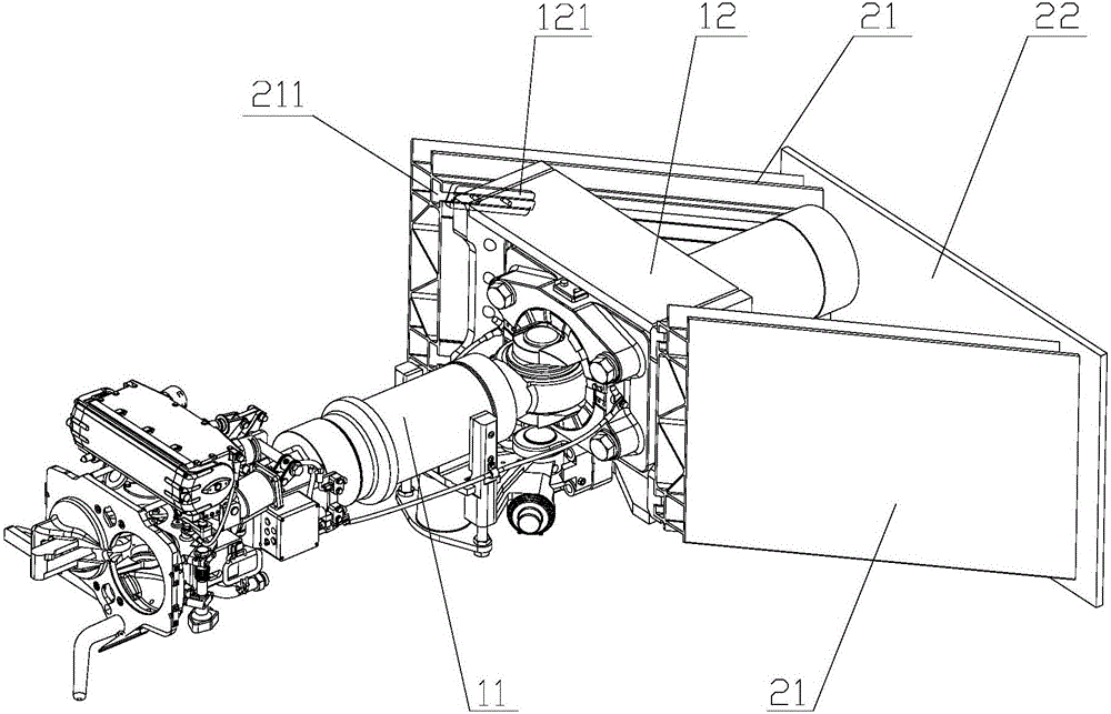
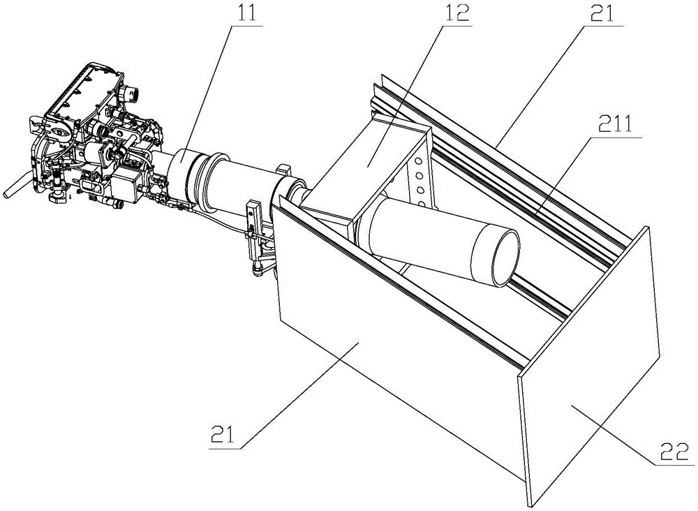
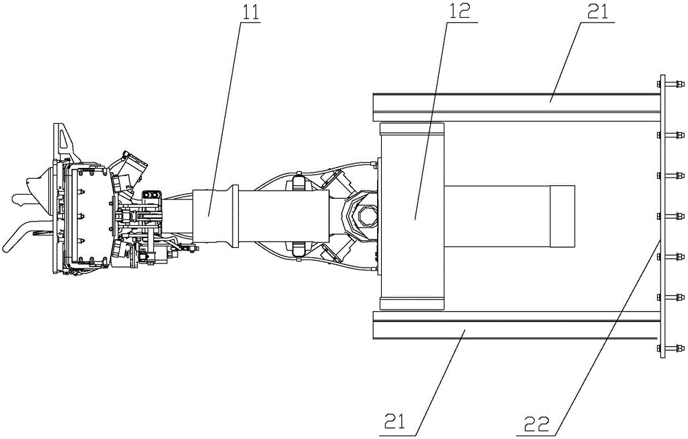
[0031] The core of the present invention is to provide a coupler assembly and a rail vehicle with the coupler assembly. The structural design of the coupler assembly can not only ensure the coupling function of the coupler when the vehicle is running normally, but also avoid the backward process of the hitched coupler when a collision occurs. The upper part of the medium intrusion guide part damages the upper equipment or falls onto the track to increase the risk of derailment, thereby improving the passive safety of rail vehicle collisions.

[0032] In order to enable those skilled in the art to better understand the solution of the present invention, the present invention will be further described in detail below in conjunction with the accompanying drawings and specific embodiments.

[0033] Please refer to Figure 1 to Figure 4 ,in, figure 1 It is a structural schematic diagram of a specific embodiment of the coupler assembly provided by the present invention; figure 2 ...


PUM


Abstract

The invention discloses a draw gear assembly and a rail vehicle with the draw gear assembly. The draw gear assembly comprises a draw gear mounting seat and a draw gear fixedly arranged on the draw gear mounting seat, and further comprises guide components arranged on two sides of the draw gear mounting seat, wherein the guide components are provided with longitudinally tilting guide sliding chutes; the front ends of the guide sliding chutes are higher than the rear ends; and sliding blocks which are in sliding fit with the guide sliding chutes in the corresponding sides are fixedly arranged on two sides of the draw gear mounting seat, and are configured as follows: under an initial state, the draw gear mounting seat is fixedly connected with the guide components, and the sliding blocks are located at the front ends of the guide sliding chutes. The structural design of the draw gear assembly can guarantee a coupling function of the draw gear during normal operation; and when collision occurs, the draw gear can neither invade the upper parts of the guide components to damage upper equipment nor fall onto a rail to increase derailing risk in the backing off and energy absorption processes, so that the passive safety of rail vehicle collision can be improved.

Description

technical field [0001] The invention relates to the technical field of rail vehicles, in particular to a coupler assembly and a rail vehicle with the coupler assembly. Background technique [0002] As the speed of high-speed rail increases, people pay more and more attention to passive safety. [0003] At present, in order to reduce the air resistance and improve the starting performance of the train, the head of the train usually adopts a streamlined tip shuttle design; although this design reduces the running resistance of the train and increases the speed of the train, the space at the front end of the train is narrow and can only accommodate In the lower coupler part, it is no longer possible to arrange a large energy-absorbing mechanism. [0004] When two high-speed trains collide, the coupler is the first to be impacted. Although the coupler can be set as an energy-absorbing coupler, its energy absorption is limited and cannot completely absorb the energy generated by...

Claims


Application Information

Patent Timeline
Patent Type & Authority Applications(China)
IPC IPC(8): B61G9/04
CPCB61G9/04
Inventor 张永贵赵士忠梁建英田爱琴丁叁叁孙现亮喻海洋车全伟李吉春董丽
Owner CRRC QINGDAO SIFANG CO LTD
Why Eureka
Try Eureka