Chain cycle load device

A chain circulation and loading technology, which is applied in the direction of transportation, packaging, conveyors, etc., can solve problems such as chain failure, chain breakage, and insufficient dynamic load, and achieve the effects of reducing chain elongation, prolonging service life, and improving reliability

Active Publication Date: 2017-01-11
张家港建辰机械科技有限公司
View PDF10 Cites 0 Cited by
  • Summary
  • Abstract
  • Description
  • Claims
  • Application Information

AI Technical Summary

Problems solved by technology

The use of small pitch chains can make the movement stable, but the dynamic load is insufficient, while the use of large pitch chains can ensure the dynamic load, but the movement stability is poor
Cyclic loading devices often have to operate under unfavorable working conditions such as heavy cargo eccentric load, fast circulation, frequent start and stop, forward and reverse rotation, and open oil-free. Chains, unstable movement and insufficient dynamic load will lead to chain link wear and elongation, and also include chain plate fatigue, chain hinge gluing, etc., which may eventually lead to chain failure, and elongation is the main form of chain failure
For various cyclic loading devices, if the failed chain is not replaced, the entire device must be discarded, and if it is replaced, it means that the device must be completely dismantled, and the manpower, material resources, financial resources and time consumed can be imagined
Not only that, the chain may break suddenly during operation and cause serious accidents
Various efforts have been made in many existing technologies, including strengthening the chain plate, anti-wear and anti-friction of the chain hinge, and enhanced lubrication, etc., but it is difficult to balance the dilemma of stable movement and guaranteed load bearing

Method used


Image

  • Chain cycle load device
  • Chain cycle load device
  • Chain cycle load device

Examples


Embodiment 1

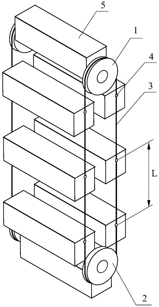
[0052] In order to solve the defect in the prior art that the chain is elongated due to long-term use, the invention discloses a chain circulation carrying device, such as figure 2 As shown, it includes two rows of endless chains 3 running in parallel and in the same direction. The two rows of endless chains 3 are installed on the sprocket set. When the endless chain 3 is a horizontal loop, the sprocket set includes left and right sprockets, and When the endless chain 3 circulates up and down, it includes the upper sprocket 1 and the lower sprocket 2, and a plurality of warehouses 5 are suspended at the same hanging distance between the two rows of endless chains 3. The hanging distance described here refers to the The number of links of the circular chain 3 between the warehouses 5, in figure 1 with figure 2 Indicated by L, the loading device also includes two closed rod chain rings corresponding to the two endless chains 3 one by one, the rod chain rings include several c...

Embodiment 2

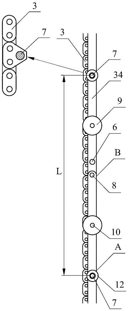
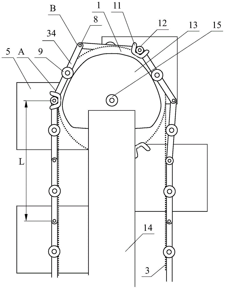
[0054] Such as image 3 As shown, this embodiment is further improved on the basis of embodiment 1, and the two functions of transmitting motion and bearing are separated, and the circulating chain 3 only transmits motion, while the rod link is used for bearing. In the present embodiment, the sprocket set includes an upper sprocket 1 and a lower sprocket 2 which are rotatably mounted on the frame 14, and the endless chain 3 is installed to circulate vertically between the upper sprocket 1 and the lower sprocket 2, The frame 14 is provided with a rod chain driving mechanism for driving the circular motion of the rod chain ring. The frame 14 is provided with an upper load-bearing guide rail 13 within the closed range of the rod chain ring. The upper load-bearing guide rail 13 includes an upper load-bearing convex surface. This upper load-bearing convex surface cooperates with the middle part of the connecting rod 34 to support the middle part of the connecting rod 34 all the tim...

Embodiment 3

[0059] As a cycle loading device, it is necessary to hang the warehouse 5 as densely as possible, and this embodiment is further realized on the basis of embodiment 2.

[0060] Specifically, such as Figure 5 As shown, several suspensions for hanging the warehouse 5 are arranged on the rod chain ring, and the suspension includes a hinge rod 36 and two support rods 35, and one end of the hinge rod 36 is hinged on the rod chain ring , the other end of the hinge pole 36 is provided with a hanging hole 6, the suspension shaft 4 of the warehouse 5 is installed in the hanging hole 6, and one end of the two poles 35 is hinged to each other through the sliding hinge shaft 25, and the two poles 35 The other end is respectively hinged on the rod chain ring, and the sliding hinge shaft 25 is slidably arranged on the hinge rod 36 along the length direction of the hinge rod 36, and its specific sliding structure is as follows: Figure 5 As shown, the hinge rod 36 is provided with a strip-...


PUM


Abstract

The invention discloses a chain circulation bearing device which comprises two columns of circulation chains which are parallel and run in the same direction. The two columns of circulation chains are arranged on a chain wheel group. A plurality of freight houses are hung between the two columns of circulation chains at equal intervals. The chain circulation bearing device is characterized in that the bearing device also comprises two closed rod chain rings in one-to-one correspondence use with the two columns of circulation chains. Each rod chain ring comprises a plurality of connection rods; one end of each connection rod is a chain hinge end, and the other end is a mutual hinge end; the chain hinge ends of the adjacent two connection rods are hinged to the corresponding circulation chain through a chain hinge shaft; the mutual hinge ends of the adjacent two connection rods are hinged through a mutual hinge shaft; and the freight houses are hung on the rod chain rings at equal intervals. According to the chain circulation bearing device, cases of extension of the circulation chains are reduced under the condition of ensuring smooth operation, thereby improving reliability of the circulation chains and prolonging the service life of the chain.

Description

technical field [0001] The invention relates to a cargo handling and storage technology, in particular to a chain circulation loading device. Background technique [0002] Almost all kinds of circulating load devices used in many industrial processes use chains to transmit motion and power, of which sleeve roller chains are the most commonly used. The use of a small pitch chain can make the motion stable, but the dynamic load is insufficient, while the use of a large pitch chain can ensure the dynamic load, but the motion stability is poor. Cyclic loading devices often have to operate under unfavorable working conditions such as heavy cargo eccentric load, fast circulation, frequent start and stop, forward and reverse rotation, and open oil-free. Chains, unstable motion and insufficient dynamic load will lead to chain link wear and elongation, as well as chain plate fatigue, chain hinge gluing, etc., which may eventually lead to chain failure, and elongation is the main for...

Claims


Application Information

Patent Timeline
Patent Type & Authority Patents(China)
IPC IPC(8): B65G17/12B65G17/42
CPCB65G17/123B65G17/42B65G21/22B65G23/06
Inventor 王建生
Owner 张家港建辰机械科技有限公司
Why Eureka
Try Eureka