Low melting temperature alloys with magnetic dispersions

Inactive Publication Date: 2011-09-01
YALE UNIV
View PDF11 Cites 34 Cited by
  • Summary
  • Abstract
  • Description
  • Claims
  • Application Information

AI Technical Summary

Benefits of technology

[0016]A method is disclosed for enhancing the mechanical properties of a low melting temperature composite material comprising an alloy of about 75% by weight to about 97% by weight of tin and about 1% by weight to about 5%

Problems solved by technology

However, environmental and human health concerns have prompted the search for replacements compositions.
In addition, recent restrictions in both Japan and the European Union necessitate a switch to lead-free solder alloys.
Unfortunately, the most suitable lead-free replacement, a tin-silver based alloy with the composition of Sn-3.5% Ag, has a melting point of 220° C., nearly 40° C. higher than the Sn-37% Pb alloy's melting point of 183° C. In addition, Sn-3.5% Ag alloys requires even higher processing temperatures, which are often 30 to 40° C. above the melting point.
Similarly, another potential replacement, ti

Method used


Image

  • Low melting temperature alloys with magnetic dispersions
  • Low melting temperature alloys with magnetic dispersions
  • Low melting temperature alloys with magnetic dispersions

Examples


Embodiment Construction

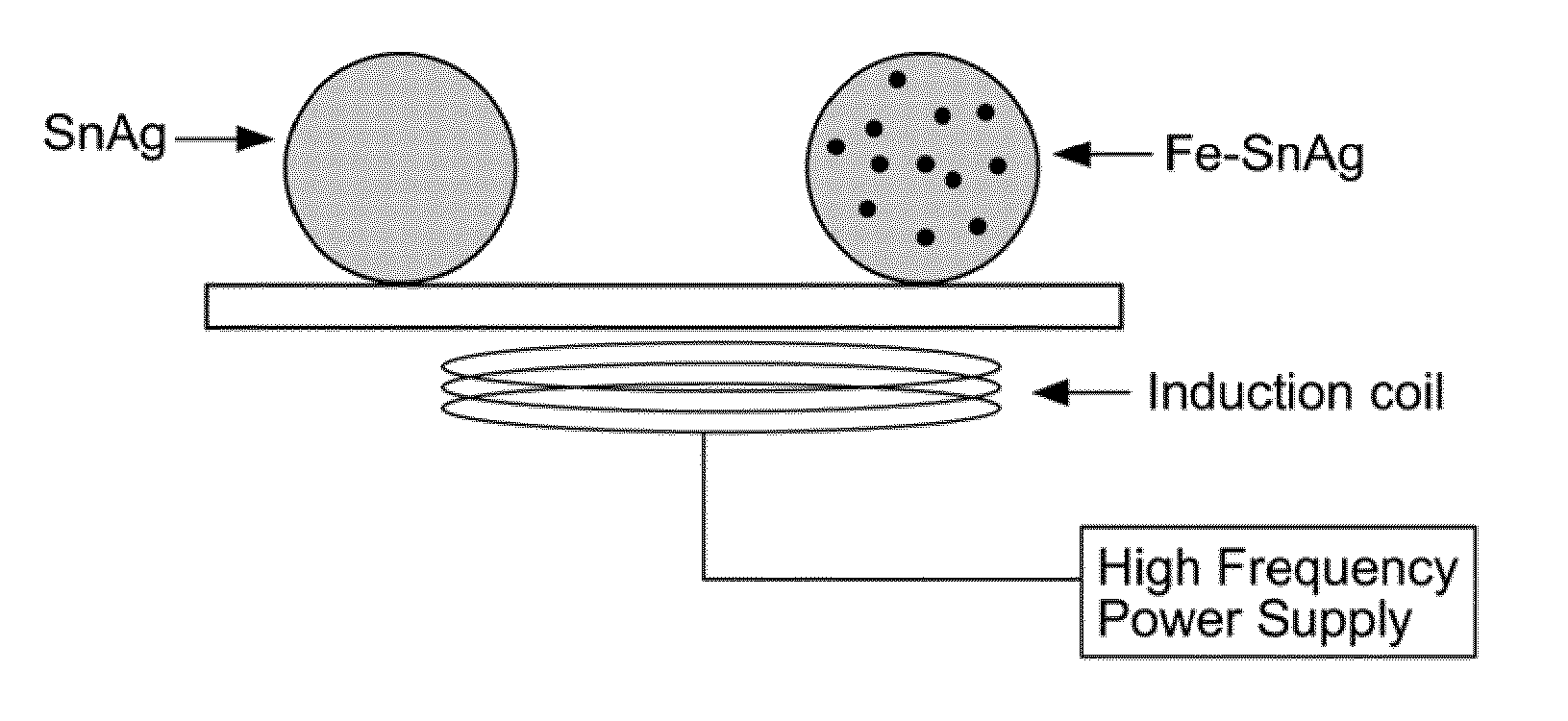
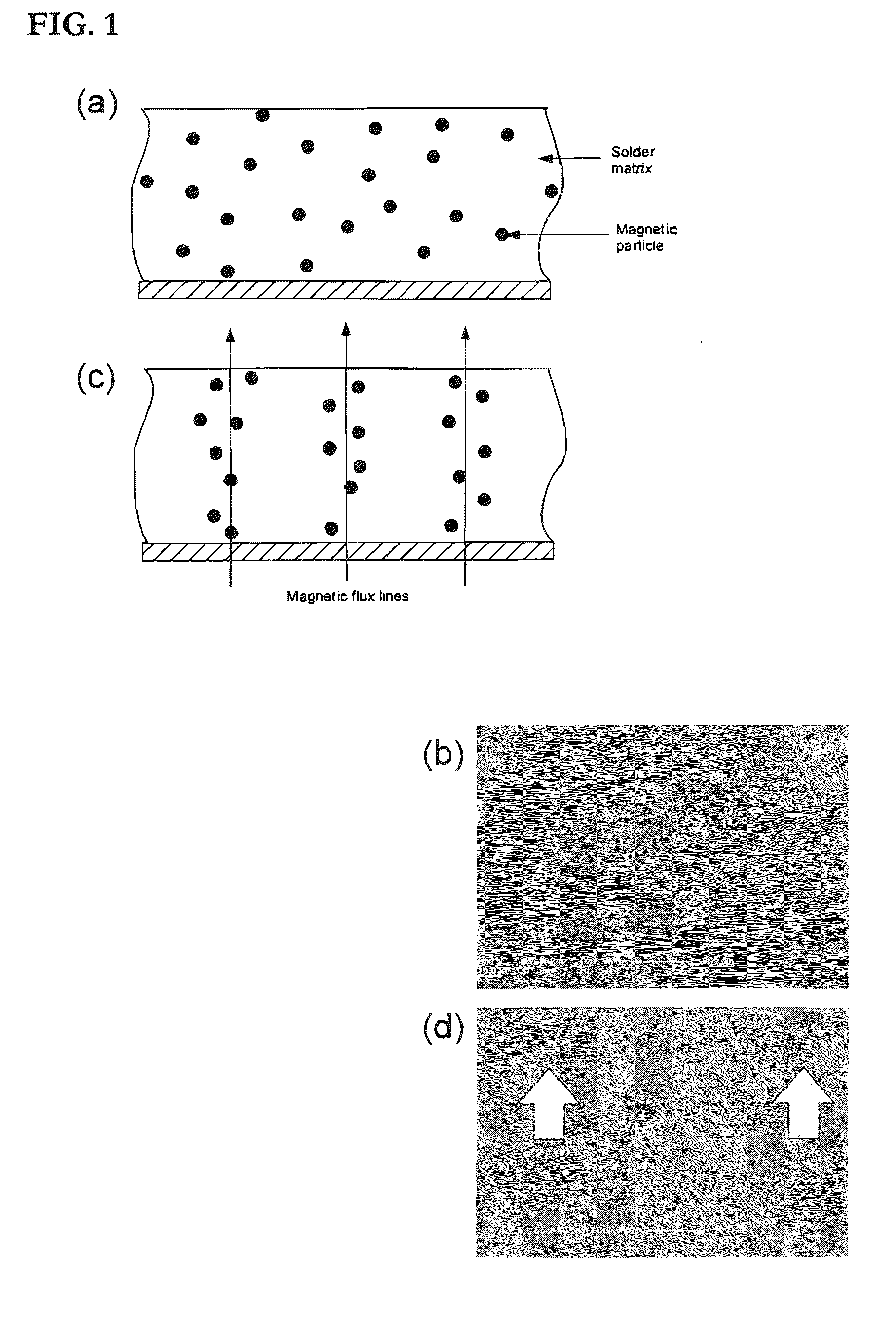
[0032]Composite materials are disclosed which include magnetic particles suspended as dispersions in low melting temperature metallic alloys such as lead-free solders. The composite lead-free solder materials have tailorable mechanical properties, the ability to be guided in three-dimensions with a magnetic field, and the ability to be heated rapidly by electromagnetic induction.

[0033]Magnetic particles may be any shape: spherical, elongated, plate-like, rod-like, nanowires, or randomly shaped. The form of the “particles” can be particles, intermetallics, separate phases, solute atoms, nanoparticles and precipitates. Typical size ranges from nanometers to 500 microns, with a preferred range of 100 nm to 100 microns. Volume fraction of the magnetic dispersoid can be from about 0.1% to about 50% with a preferred range of about 0.5 to about 20%. The form of the magnetic particles can be crystalline, amorphous, semicrystalline and nanocrystalline.

[0034]To improve the wetting of magnetic...


PUM

PropertyMeasurementUnit
Fractionaaaaaaaaaa
Fractionaaaaaaaaaa
Fractionaaaaaaaaaa

Abstract

A low melting temperature composite material including an alloy having about 0.1% by weight to about 99% by weight of tin and about 0.1% by weight to about 90% by weight of an element selected from the group consisting of silver and gold, and about 0.1% by weight to about 50% by weight of magnetic particles dispersed in the alloy. Method of heating such a composite material, remotely manipulating such a composite material with magnetic fields, enhancing the mechanical properties of such a material, and making such a material are also disclosed.

Description

CROSS-REFERENCE TO RELATED APPLICATIONS[0001]This application claims the priority of U.S. Provisional Application No. 61 / 307,590 filed on Feb. 24, 2010, which is incorporated herein by reference herein in its entirety.STATEMENT REGARDING FEDERALLY SPONSORED RESEARCH OR DEVELOPMENT[0002]This research was supported in part by U.S. Government funds (National Science Foundation Grant No. CMMI-0925994) and the U.S. Government therefore has certain rights in the invention.BACKGROUND OF THE INVENTION[0003]Solder is a ubiquitous joining material for the construction of electronics devices, serving to interconnect electronic components by providing conductive pathways. Traditional solders are lead-based alloys, and most commonly a tin-lead solder alloy (Sn-37% Pb) having about 37% lead in a tin base material. However, environmental and human health concerns have prompted the search for replacements compositions. In addition, recent restrictions in both Japan and the European Union necessitat...

Claims


Application Information

Patent Timeline
IPC IPC(8): H01F1/03B82Y25/00
CPCB22F2303/01B22F2303/05H05K2203/104H05K2203/101H05K2201/083H05K3/3494H05K3/3484H05K3/3468H05K3/3457H01F1/44H01F1/37B23K35/025B23K35/262C22C1/0483C22C13/00C22C32/001C22C2202/02H01F1/083H01F1/113H01F1/28B22F2301/30B22F2301/10B22F2301/255B22F2301/40B22F2302/20B22F2302/25B22F2302/35B22F2302/45H05K3/3485
Inventor RAMIREZ, AINISSA G.HAYES, ERIC L.
Owner YALE UNIV
Why Eureka
Try Eureka