Continuous rolling planetary mill

A planetary rolling mill and drive motor technology, applied in metal rolling, metal rolling, manufacturing tools, etc., can solve the problems of low rolling efficiency, feeding, rolling, and receiving intermittent, feeding and receiving, etc., to achieve The effect of reducing the turnover time of receiving materials, prolonging the service life and improving production efficiency

Active Publication Date: 2019-01-04
GUANGDONG HAILIANG COPPER IND CO LTD +1
View PDF9 Cites 0 Cited by
  • Summary
  • Abstract
  • Description
  • Claims
  • Application Information

AI Technical Summary

Problems solved by technology

Therefore, in this working process, when the hollow cast slab is loaded, it is necessary to pass through the cast slab through the core rod, and then push the hollow cast slab into the planetary host for rolling through the push trolley. After the rolling is completed, the push trolley can Drive the mandrel to withdraw from the slab to realize the turning and winding of the slab. In this way, the push trolley cannot return to continue loading the next hollow slab during the period from the start of slab loading to the completion of slab rolling. This will inevitably cause the discontinuity of feeding, rolling, and receiving, that is, the planetary main machine is in an idle state during the process of returning the pushing trolley and conveying the slab, and the rolling process of the planetary main machine There is no material loading to undertake in
[0003] Therefore, due to the above-mentioned structure of the existing planetary rolling mill, not only the rolling efficiency is low, but also because of the intermittent rolling of the planetary main machine, it is easy to bring a certain impact to the planetary main machine, which affects the service life of the planetary rolling mill

Method used


Image

  • Continuous rolling planetary mill
  • Continuous rolling planetary mill
  • Continuous rolling planetary mill

Examples


Embodiment 1

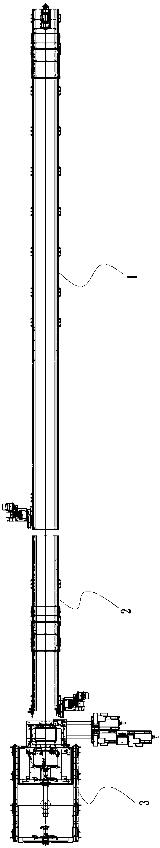
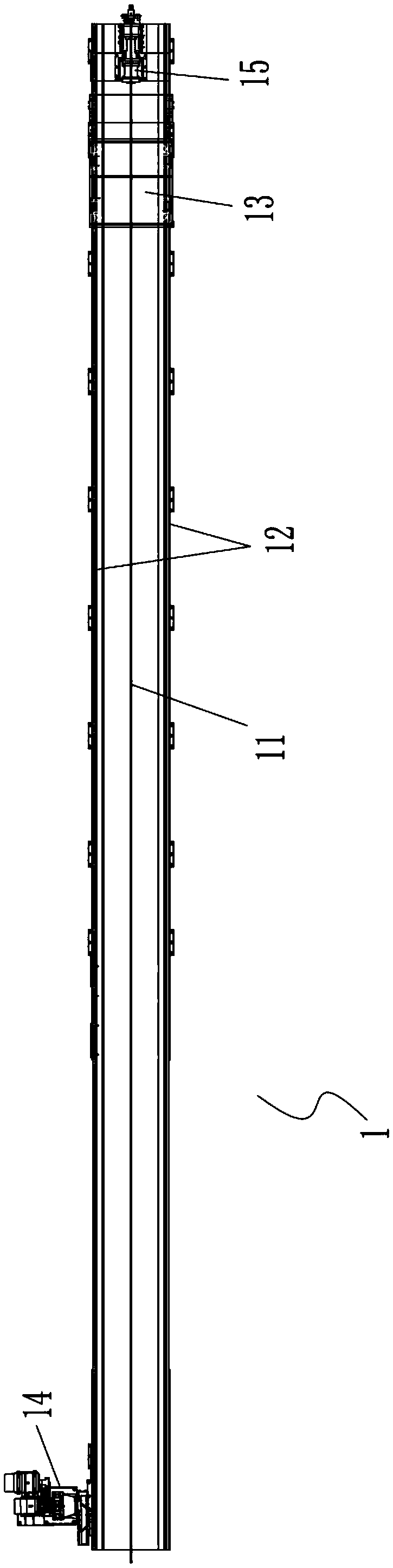
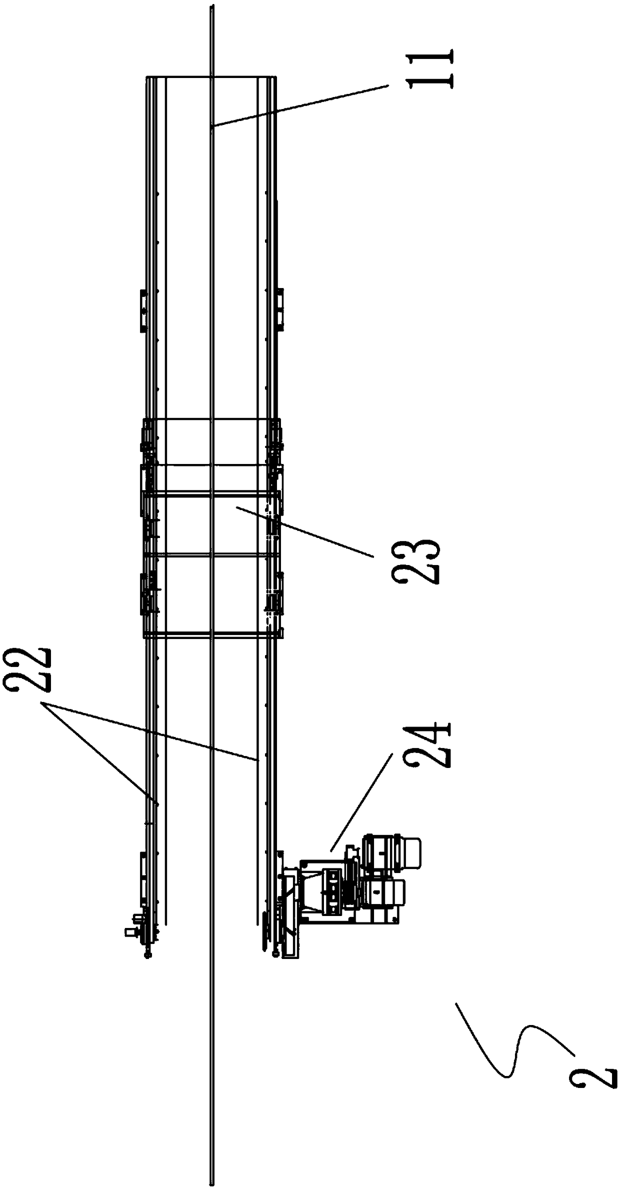
[0032] see figure 1 , The present invention provides a continuous rolling planetary rolling mill, which includes a first feeding mechanism 1, a second feeding mechanism 2 and a rolling mechanism 3 arranged sequentially from one side to the other according to the sequence of stations. The first feeding mechanism 1 pushes the received material to be rolled to the second feeding mechanism 2, and returns to its initial station to continue receiving the next material to be rolled after the material is advanced; The second feeding mechanism 2 advances the material received from the first feeding mechanism 1 to the rolling mechanism 3, and returns to its initial station after completing the material advancement to continue to accept the materials advanced by the first feeding mechanism 1. The next material to be rolled.

[0033] Thus, through the cooperative work of the two feeding mechanisms, the first feeding mechanism 1 can continue to load and feed materials while the second fee...

Embodiment 2

[0045] The structure of this embodiment is basically the same as that of Embodiment 1. The difference is that in this embodiment, in order to enhance the stability of material transportation between the two feeding mechanisms and further improve the continuity and efficiency of material transportation, please refer to Figure 4 , The second feeding mechanism 2 further includes a rotary chuck 25;

[0046] In order to ensure better and faster conveying of the slab and avoid affecting the feeding efficiency due to misalignment, as a more optimal technical solution, the axis of the rotary chuck 25 of the second feeding mechanism 2, the axis of the first feeding The axis of the rotary chuck 25 of the feeding mechanism 1 and the axis of the core rod 11 are collinear.

[0047] Then in the feeding process, the core rod 11 is first clamped by the rotary chuck 25 of the second feeding mechanism 2, when the feeding trolley 13 of the first feeding mechanism 1 clamps the cast slab and push...

Embodiment 3

[0049] The structure of this embodiment is basically the same as that of Embodiment 2, the difference is that in this embodiment, in order to further improve feeding efficiency and rolling efficiency, please refer to Figure 5 and Figure 6 , as a more optimal technical solution, the continuous rolling planetary rolling mill of the present invention also includes a storage rack 4 and a conveying roller table 5 . The storage rack 4 transports the material to be rolled stored thereon to the conveying roller table 5 , and is output to the first feeding mechanism 1 by the conveying roller table 5 .

[0050] In this embodiment, since the storage rack 4 has the same structure as the existing storage rack for storing and turning over the hollow cast slab, and the conveying roller table 5 is the same as the existing conveying roller table for conveying the hollow cast billet to the feeding mechanism , so it will not be repeated here.

[0051] Then in the feeding process, the casting...


PUM


Abstract

The invention relates to a continuous rolling planetary rolling mill. A first feeding mechanism, a second feeding mechanism and a rolling mechanism are sequentially arranged from one side to the other side according to the sequence of stations. The first feeding mechanism pushes a received to-be-rolled material to the second feeding mechanism, returns to the initial station after pushing the materials and continues to receive the next to-be-rolled material. The second feeding mechanism pushes the material received from the first feeding mechanism to the rolling mechanism, returns to the initial station after pushing the material and continues to receive the next to-be-rolled material pushed by the first feeding mechanism. The overturning time of ingots, time for pushing and returning of a feeding trolley, and time for a core bar to penetrate through the ingots and return are shortened, feeding continuity and rolling continuity of the materials are achieved, rolling efficiency is greatly improved, impact to the rolling mechanism is reduced, and the service life of the rolling mill is prolonged.

Description

technical field [0001] The invention relates to the field of metallurgical rolling, in particular to a continuous rolling planetary rolling mill. Background technique [0002] Existing planetary rolling mills generally include a feeding mechanism for conveying hollow slabs and a planetary host for casting hollow slabs. The feeding mechanism consists of a conveying platform and a propulsion mechanism arranged on the top of the conveying platform and used to push forward the hollow cast slab. The propulsion mechanism is composed of a core rod with a core rod, a push head for pushing the core rod forward, and a push trolley for pushing the hollow cast slab forward. Then, in the working process of the existing planetary rolling mill, the pusher will send the mandrel with the mandrel into the hollow casting slab and withstand the hollow casting slab, and send it to the roll group of the planetary main machine together, and wait for the planetary main machine to roll. , Rolled p...

Claims


Application Information

Patent Timeline
Patent Type & Authority Patents(China)
IPC IPC(8): B21B1/42B21B39/00B21B39/02
CPCB21B1/42B21B39/002B21B39/02
Inventor 党建龙马为民凌金榜白文侠邱长军秦备荒刘涛王刚纯
Owner GUANGDONG HAILIANG COPPER IND CO LTD
Why Eureka
Try Eureka