
Sheet bending device

A bending device and thin plate technology, which is applied in the field of thin plate bending devices, can solve the problems of difficult removal of thin plates, high manual labor intensity, and failure to meet product quality requirements, so as to meet the requirements of mass processing and production with low manual labor intensity , Guarantee the effect of plate performance

Inactive Publication Date: 2017-02-15
讯龙型材折弯(合肥)有限公司
View PDF6 Cites 10 Cited by
  • Summary
  • Abstract
  • Description
  • Claims
  • Application Information

AI Technical Summary

Problems solved by technology

[0004] In the existing bending technology, most of the bending machines are used to directly bend the plate, and the bending of the large and thin plate is relatively thin, so the bending machine is directly used for bending, and the force applied during bending Only focus on the bending position of the thin plate. Because it is relatively thin, the performance of the plate at the bending position is very poor, easy to deform and damage, and cannot meet the product quality requirements. Moreover, it is not easy to take out the thin plate after bending. In order to ensure that it does not deform after taking out , needs to be manually operated slowly, the process is labor-intensive, time-consuming and labor-intensive, and the work efficiency is low

Method used


Image

  • Sheet bending device

Examples


Embodiment Construction

[0017] See attached picture.

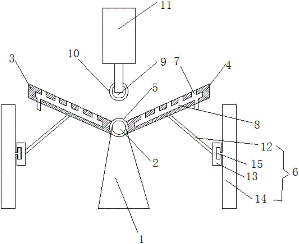
[0018] A thin plate bending device, comprising a base 1, a fixed shaft 2 is installed in the middle of the base 1, flip plates 3 and 4 that rotate around the fixed shaft are installed on both sides of the fixed shaft 2, and the inner sides of the flip plates 3 and 4 are provided with The shaft sleeve 5 that cooperates with the fixed shaft 2, and the shaft sleeves of the two flaps 3 and 4 are set at a dislocation interval. A plurality of air outlet holes 7 are distributed, and the air outlet holes 7 extend into the flaps 3 and 4, and are communicated with the vent chambers 8 in the flaps 3 and 4, and the air inlets of the vent chambers 8 are connected with air inlet pipes respectively, and the fixed shaft 2 is erected with finale 9 directly above, and axle sleeve 10 is sleeved on finalist 9, and institute axle 9 is driven by the cylinder 11 of its upper end.

[0019] The guide rod slider mechanism 6 includes a guide rod 12 hinged on the lower end...


PUM


Abstract

The invention discloses a sheet bending device which comprises a base. A fixing shaft is installed at the middle portion of the base. Overturning plates rotating around the fixing shaft are installed on the two sides of the fixing shaft. The inner side of each overturning plate is provided with a shaft sleeve matched with the fixing shaft. The shaft sleeves of the two overturning plates are arranged in a spaced and staggered manner. Overturning of the overturning plates is driven by guide rod sliding block mechanisms on the outer sides of the overturning plates. Multiple air outlet holes are distributed in the overturning plates. The air outlet holes stretch in the overturning plates and communicate with ventilation cavities in the overturning plates. Air inlets of the ventilation cavities communicate with air inlet pipes correspondingly. A pressing shaft is erected over the fixing shaft and is sleeved with a shaft sleeve, and the pressing shaft is driven by an air cylinder at the upper end of the pressing shaft. According to the sheet bending device, the overturning plates on the two sides are used for overturning sheets, the stress position and the stress direction of the sheets are changed, the performance at bend positions of the sheets is ensured, the bending requirements are met, the manual labor intensity in the process is low, time and labor are saved, the work efficiency is high, and the requirement for large-batched machining and production is met.

Description

[0001] Technical field: [0002] The invention relates to the field of bending equipment, and mainly relates to a sheet bending device. [0003] Background technique: [0004] In the existing bending technology, most of the bending machines are used to directly bend the plate, and the bending of the large and thin plate is relatively thin, so the bending machine is directly used for bending, and the force applied during bending Only focus on the bending position of the thin plate. Because it is relatively thin, the performance of the plate at the bending position is very poor, easy to deform and damage, and cannot meet the product quality requirements. Moreover, it is not easy to take out the thin plate after bending. In order to ensure that it does not deform after taking out , It needs to be manually operated slowly, and the process is labor-intensive, time-consuming and labor-intensive, and the work efficiency is low. [0005] Invention content: [0006] The object of the ...

Claims


Application Information

Patent Timeline
Patent Type & Authority Applications(China)
IPC IPC(8): B21D5/16
CPCB21D5/16
Inventor 房建华
Owner 讯龙型材折弯(合肥)有限公司
Learn More