A cutting machine tool for crankshaft connecting rod production

A technology for cutting machine tools and crankshafts and connecting rods, which is applied in the direction of sawing machine devices, metal sawing equipment, and metal processing equipment. The effect of reducing the labor intensity of workers

Active Publication Date: 2018-05-15
重庆昌跃机电制造有限公司
View PDF6 Cites 0 Cited by
  • Summary
  • Abstract
  • Description
  • Claims
  • Application Information

AI Technical Summary

Problems solved by technology

Since the connecting rod body and the connecting rod cover mostly adopt the die-casting process, in order to improve efficiency, multiple connecting rod cores are usually set in the mold, so that multiple connecting rod workpieces can be die-casted at one time and these multiple workpieces need to be connected through reserved connecting rods. For an integrated blank, after the blank is taken out from the mold and cooled, the workpiece needs to be cut off from the blank. In the prior art, workers mostly use connecting rods to cut the blank. The disadvantage is that on the one hand Workers are prone to fatigue if they hold the blank for a long time. The labor intensity of the workers is high, and there are also potential safety hazards. At the same time, it is difficult to ensure the accuracy of the cut manually, which may easily cause unqualified waste parts.

Method used


Image

  • A cutting machine tool for crankshaft connecting rod production
  • A cutting machine tool for crankshaft connecting rod production
  • A cutting machine tool for crankshaft connecting rod production

Examples


Embodiment Construction

[0018] The technical solutions in the present invention will be further described below in conjunction with the accompanying drawings and embodiments.

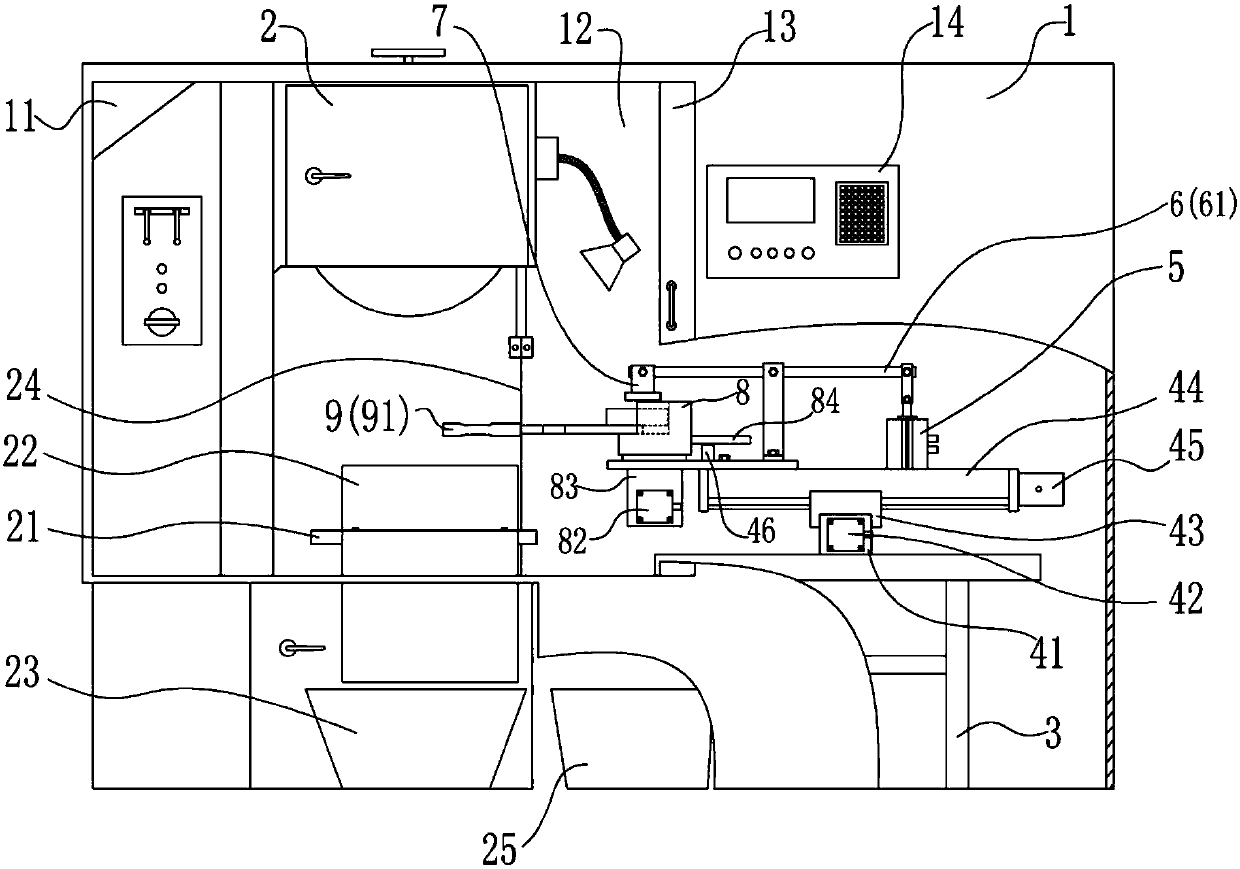
[0019] Such as figure 1 As shown, the present invention proposes a cutting machine tool for the production of crankshaft connecting rods, including a box body 1 and a sawing machine 2 arranged in the inner cavity of the box body 1, a clamping device and a numerical control host 14, wherein: the box body 1 A sawing machine operation window 11 and a clamping operation window 12 are provided, wherein a movable protective door 13 is provided at the clamping operation window 12, and the sawing machine 2 and the clamping device can be closed in by setting the box body 1 when idle, thereby avoiding The sawing machine 2 is damaged or accidentally injured;

[0020] The sawing machine 2 is a vertical sawing machine using a band saw blade 24, a hopper 22 is provided on the workbench 21 of the sawing machine 2, and a material box 23 is p...


PUM


Abstract

The invention provides a cutting machine tool for crankshaft connecting rod production. The cutting machine tool comprises a compartment body, a sawing machine, a clamping device, a numerical control main unit, a hopper and a material box, wherein the compartment body is provided with a sawing machine operation window and a clamping operation window; the clamping device comprises a support, a cross sliding table, a cylinder, a lever structure, a pressing block, a limiting block and a rotatable servo motor; both a Y-axis sliding rail and an X-axis sliding rail of the cross sliding table are arranged horizontally, and are connected through a sliding block; a Y-directional screw rod structure and a Y-directional servo motor are arranged in the Y-axis sliding rail; an X-directional screw rod structure and an X-directional servo motor are arranged in the X-axis sliding rail; the lever structure and the cylinder are fixed above the X-axis sliding rail; two ends of a lever are respectively connected with a telescopic rod of the cylinder and the pressing block in a hinged manner; the limiting block is arranged on the X-axis sliding rail and is connected with the rotatable servo motor through a transmission mechanism; and the numerical control main unit is electrically connected with the rotatable servo motor, the Y-directional servo motor and the X-directional servo motor. The cutting machine tool for crankshaft connecting rod production reduces the labor intensity of a worker, eliminates the potential safety hazards and guarantees the quality of a workpiece.

Description

technical field [0001] The invention relates to the field of mechanical manufacturing, in particular to a cutting machine tool used in the production of crankshaft connecting rods. Background technique [0002] Crankshaft-connecting rod mechanism is a transmission mechanism widely used in engines and motors. It is used to realize the power transmission between the linear reciprocating motion of the piston and the rotary motion of the crankshaft. The connecting rod is a rod-shaped rod directly connected between the piston and the crankshaft. The structure generally includes a small end, a shaft and a large end. The small end of the connecting rod is used to connect the piston pin, the large end of the connecting rod is used to connect with the crank pin of the crankshaft, and the shaft is used to connect the small end and the large end. The large head is designed as a split type, and the separated part is the connecting rod cover. During production, the connecting rod body an...

Claims


Application Information

Patent Timeline
Patent Type & Authority Patents(China)
IPC IPC(8): B23D53/00B23D55/04
CPCB23D53/00B23D55/04
Inventor 温昌明张跃
Owner 重庆昌跃机电制造有限公司
Why Eureka
Try Eureka