
Mold releasing mechanism

A technology of demolding mechanism and sliding seat, which is applied to household components, household appliances, other household appliances, etc., can solve problems such as product sticking to the top block.

Inactive Publication Date: 2017-02-15
KUNSHAN HONGYONGSHENG MOLD
View PDF5 Cites 1 Cited by
  • Summary
  • Abstract
  • Description
  • Claims
  • Application Information

AI Technical Summary

Problems solved by technology

[0006] The purpose of the present invention is to overcome the shortcomings of the prior art and provide a demoulding mechanism that can effectively optimize the mold structure and overcome the problem of product adhesion to the top block during demoulding

Method used


Image

  • Mold releasing mechanism
  • Mold releasing mechanism

Examples


Embodiment

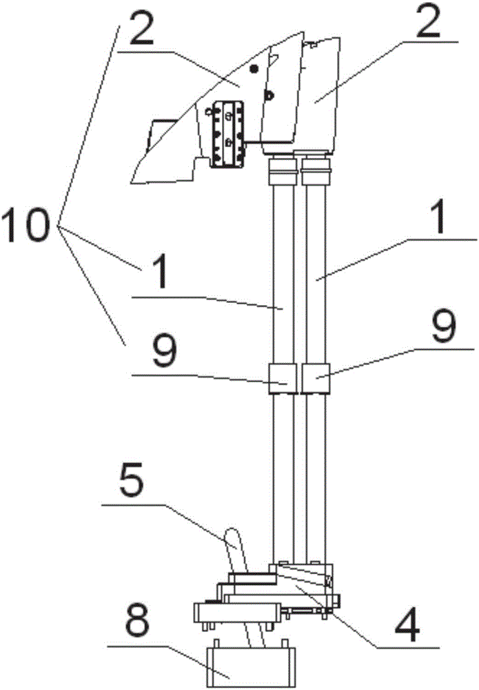
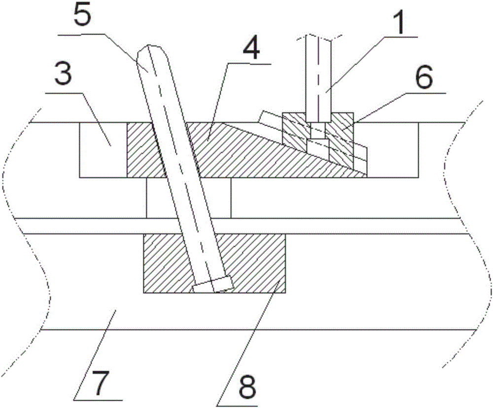
[0023] Example: such as figure 1 As shown, this embodiment provides a specific embodiment of a demoulding mechanism, and the demoulding mechanism is suitable for being installed in a mold for molding an automobile bumper.

[0024] refer to figure 1 and figure 2 , the demoulding mechanism includes a ejector rod device 10 for ejecting products, the ejector rod device 10 includes a straight ejector rod 1 connected to a ejector block 2 arranged at one end of the straight ejector rod 1 . We define that the end where the top block 2 is located is the upper side, then the top block 2 is connected to the upper end of the straight ejector rod 1 for ejecting the product. The ejector rod device 10 also includes a ejector rod fixing seat 6 and a ejector rod guide sleeve 9 arranged at the lower end of the straight ejector rod 1 . Wherein, the ejector rod holder 6 is used to fix the straight ejector rod 1, and the ejector rod guide sleeve 9 plays a guiding role for the straight ejector ...


PUM


Abstract

The invention discloses a mold releasing mechanism. The mold releasing mechanism comprises a centre plate, an ejection rod device used for ejecting products, a sliding base embedded into the centre plate and an inclined guide rod penetrating into the sliding base, wherein the inclined guide rod is fixedly arranged, the ejection rod device is movably connected to one end of the sliding base, when the centre plate ejects the products upwards, the sliding base slides in the centre plate and moves upwards along the inclined guide rod, and the ejection rod device slides downwards relative to the sliding base. Compared with the prior art, the mold releasing mechanism has the advantages that under the cooperative driving effect of the sliding base and the inclined guide rod, ejecting and falling of the ejection rod device can be simultaneously realized in the ejection driving process of the centre plate, namely the upward ejection displacement of the ejection rod device is smaller than the ejection displacement of other ejection parts such as the sliding base, and therefore the products do not adhere to ejection blocks after ejected and can be normally taken out, pull damage to the products is avoided, the structure integrity of the products is guaranteed, the appearances of the products are flawless, and the injection molding period of the products can be shortened further.

Description

technical field [0001] The invention belongs to the field of mold design, in particular to a demoulding mechanism. Background technique [0002] The car bumper is a safety device that absorbs and eases external impact and protects the front and rear of the car body. Plastic bumpers are commonly used at present, which are made by injection molding. Plastic bumpers have strength, rigidity and decoration. From the perspective of safety, they can play a buffer role in the event of a car collision and protect the front and rear bodies. It has a good decorative effect and becomes an important part of the appearance of the car. [0003] Generally, the product structure of bumper is relatively complicated. When demoulding after injection molding, the product is prone to sticking to the mold and the top block after ejection, which makes the product unable to be picked up smoothly. Seriously, it will be strained when the product is removed. products, affecting product quality. [...

Claims


Application Information

Patent Timeline
Patent Type & Authority Applications(China)
IPC IPC(8): B29C45/40B29L31/30
CPCB29C45/4005B29L2031/3044
Inventor 邹强
Owner KUNSHAN HONGYONGSHENG MOLD
Learn More