Click on the blue label to locate the original text in one second.
Reading with bidirectional positioning of images and text.
Examples
Embodiment Construction
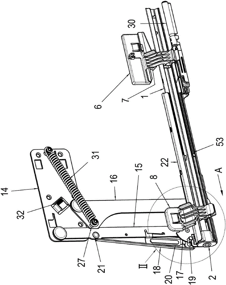
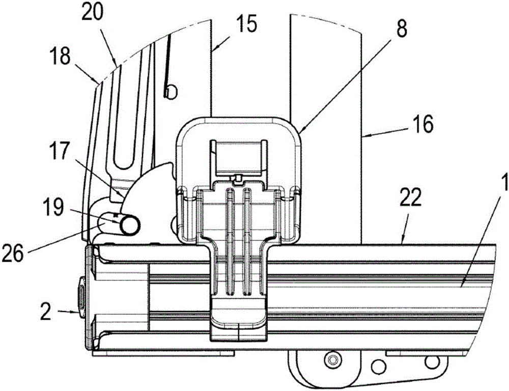
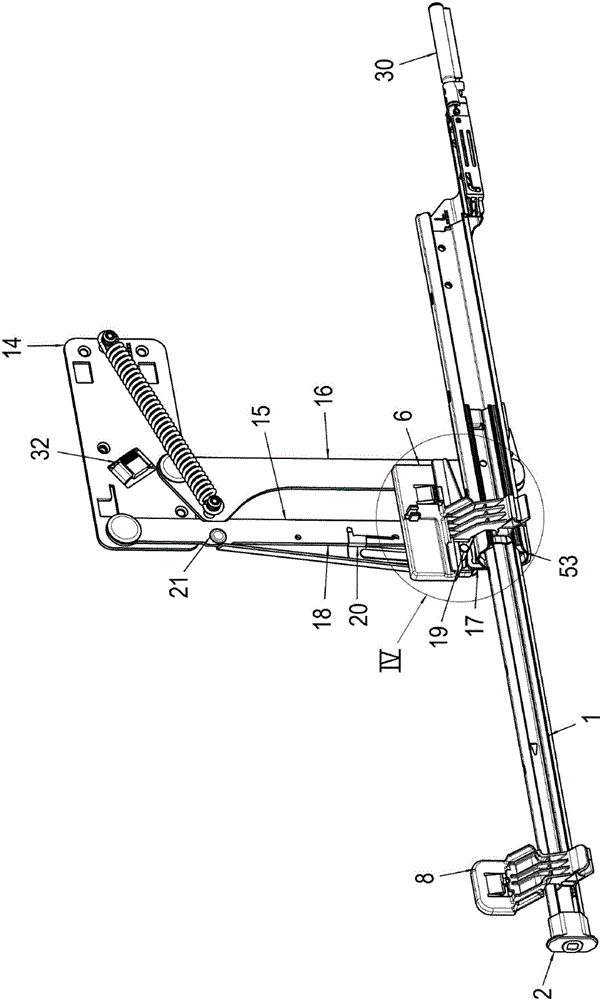
[0036] In the following description of the figures, terms such as top, bottom, left, right, front, rear, etc. only refer to the corresponding illustrations and positions of sliding pivot mechanisms, pivot arms, guide rails, running rails, actuators, etc., These illustrations and positions are chosen as examples in the description. These terms are not to be understood as limiting, ie these references may change in different operating positions or due to mirror-symmetrical designs, etc.
[0037] Figure 1 to Figure 13 An embodiment of the sliding pivot mechanism according to the invention is shown, wherein exemplary positions of the sliding pivot mechanism during the lifting process and the subsequent lowering process are shown.
[0038] For example figure 1 As shown in , the slide pivot mechanism comprises two pivot arms 15, 16 arranged parallel to each other and spaced apart from each other.
[0039] The pivot arms 15, 16 are fastened at first ends to the side wall holder 1...
PUM
Abstract
The invention relates to a sliding-pivoting mechanism of a shelf (34) of a piece of furniture or of a domestic appliance for pulling out and raising the shelf (34) from a body of the piece of furniture or from a useful space of the domestic appliance, in particular a dishwashing appliance, comprises a first pivot arm (15), which is fastened to at least one of the side walls of the body or of the useful space by means of a first end in such a way that the first pivot arm can be rotated parallel to the plane of the side walls, a second pivot arm (16), which is fastened to the at least one of the side walls of the body or of the useful space by means of a first end in such a way that the second pivot arm can be rotated parallel to the plane of the side walls, wherein the pivot arms (15, 16) are arranged parallel to each other at a distance from each other, wherein a guide rail (22) is fastened to second ends of the pivot arms (15, 16) in such a way that the guide rail can be pivoted parallel to the plane of the side walls and that the guide rail (22) can be pivoted from a lower position inside the body or the useful space to a raised, upper position at least partially outside the body or the useful space, and at least one running rail (1), which can be moved linearly in the guide rail (22) and to which the shelf (34) is fastened, wherein the sliding-pivoting mechanism comprises a locking mechanism for preventing a pivoting motion of the sliding-pivoting mechanism in a raised and a lowered end position, which locking mechanism is arranged on the guide rail (22) and on one of the pivot arms (15, 16) and can be actuated by means of an activator (6) fastened to the running rail (1), wherein the locking mechanism comprises a web (18), which is retained on the first pivot arm (15, 16) in a pivotable and resilient manner and has a pin (19) protruding in the direction of the guide rail (22), which pin can be guided along a guiding element (17) fastened to the guide rail (22) from the locking position securing the lowered end position at least to the locking position securing the raised end position, wherein the activator (6) fastened to the running rail (1) has a curve guide, by means of which the pin (19) can be guided from the locking position securing the lowered end position to the locking position securing the raised end position and back during the raising and lowering of the shelf (34). The invention further relates to a piece of furniture having a sliding-pivoting mechanism and to a domestic appliance having a sliding-pivoting mechanism.
Description
technical field [0001] According to the preamble of claim 1 , the invention relates to a sliding pivot mechanism of a shelf of furniture or a household appliance for pulling or lifting the shelf from the body of the furniture or from the useful space of the household appliance. The invention also relates to furniture and household appliances with a sliding pivot mechanism. Background technique [0002] Such a sliding pivot mechanism is particularly installed to improve the suitability of furniture or household appliances, in particular dishwashers or cooking appliances. A shelf installed in such a piece of furniture or a household appliance can be moved by pulling out and subsequent upward pivoting by means of a sliding pivot mechanism from a bottom position to an upward position where the user can conveniently place items on a shelf, or remove items placed on said shelf. [0003] A generic sliding pivot mechanism is known, for example, from WO 2014 / 03 3092 A1. [0004] T...
Claims