Anchor with separate mixing and discharge heads

A technology of mixing head and bolt, used in the installation of bolts, mining equipment, earth-moving drilling, etc., can solve the problems of not containing at the same time, insufficient parts, impossible, etc., to ensure stability and prevent blocking or damage.

A technology of mixing head and bolt, used in the installation of bolts, mining equipment, earth-moving drilling, etc., can solve the problems of not containing at the same time, insufficient parts, impossible, etc., to ensure stability and prevent blocking or damage.

CN102482942BInactive Publication Date: 2016-01-13MINOVA INT

Image

  • Anchor with separate mixing and discharge heads
  • Anchor with separate mixing and discharge heads
  • Anchor with separate mixing and discharge heads

Examples


Embodiment Construction

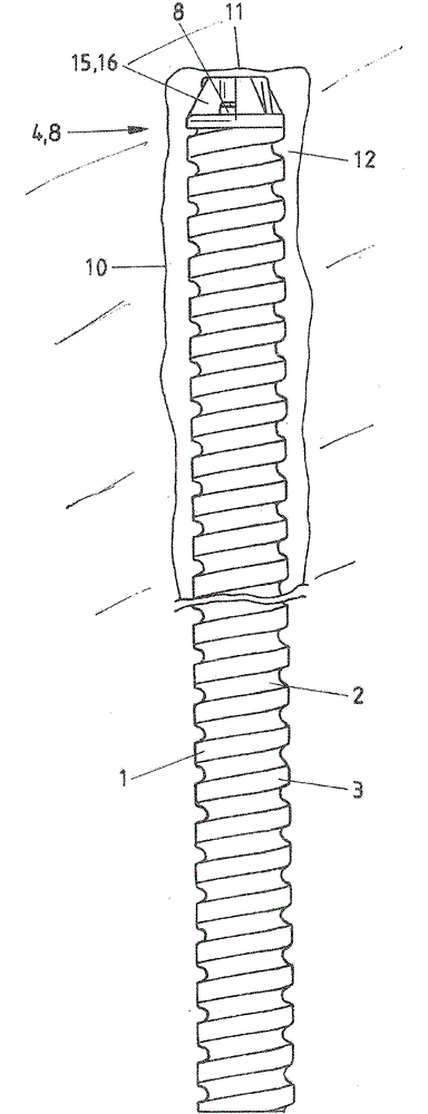
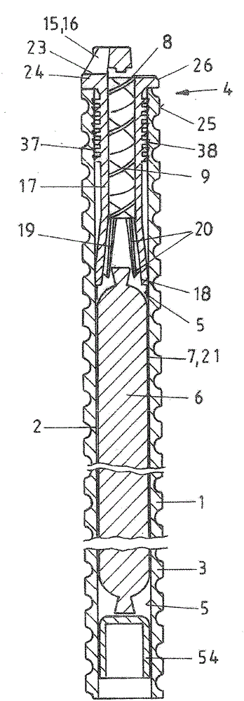
[0047] The bolt tube 2 is hollow with an internal channel 5 and has an inlet (not shown) and an outlet in the form of a discharge end 4 . The bolt tube 2 is fitted on the outside by means of an outer rib 3 . The injection plunger 54 is placed in the inner passage 5 of the bolt tube 2 adjacent to the inlet of the bolt tube 2, so that the anchor box 7 (or the multi-chamber anchor box 21) is arranged between the injection plunger 54 and the mixing head 15. Inside Passage 5. The injection plunger 54 is movable along the inner channel 5 . In use, the jetting plunger 54 may be used to load the anchor cartridge 7 , 21 in the bolt tube 2 .

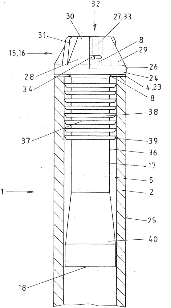
[0048] The mixing head 15 has an attachment 17 for opening the anchor box, a static mixer 9 , a support plate 24 , a head 16 forming the outlet opening 8 .

[0049] Arranged on the discharge end 4 of the bolted tube 2 is a mixing head 15 with an integral outlet orifice 8 . In fact, this outlet hole 8 is a continuation of the internal channel 5...


PUM


Abstract

Rock bolts (1) exist in various forms, wherein it is particularly advantageous if the discharge end (4) is provided with a mixing head (15), into which the required exit hole (8) is integrated. This exit hole (8) is protected by the shape of the head (16) of the mixing head (15) in such a way that a reliable discharge of the anchoring mixture is always guaranteed even if there are drillings still situated in the borehole. Furthermore, the anchoring cartridge (7) upon the application of pressure is reliably torn open so that the two components pass into the region of the static mixer (9) and are then discharged in the mixed state so that the cavity (12) around the bolt tube (2) is reliably filled.

Description

technical field [0001] The present invention relates to a rockbolt in the form of an anchoring bolt having an externally shaped bolt tube in relation to an anchoring compound charge housed, for example, in an anchoring box , and the anchoring compound charge can be ejected from the bolt tube through a static mixer with an injection plunger, wherein the discharge end of the bolt tube to be set in the end of the borehole has one or more outlet holes . Background technique [0002] Various forms of bolts are known and are primarily used to stabilize rock in corridors and roads and in the area around tunnels. In the case of the rock bolts known from DE10017750A1 and WO03 / 044324A1, before this a borehole is drilled in the rock with a drill pipe in a first working step, after reaching the final length, it is replaced with a continuous inner Open bolt tube. The anchor box is inserted into the inner opening of the bolt tube, and in front of the anchor box is a static mixer, so th...

Claims


Application Information

Patent Timeline
13 Jan 2016
Publication
CN102482942B
IPC
E21D20/02
CPC
E21D20/02; E21D20/023; E21D20/026
Inventors
汉斯-δΉ”ζ²»Β·ζ‹œε°”; ι©¬εΊ“ζ–―Β·ζ–―ζ²ƒεšθΎΎ