
Locking device and electric automobile

A technology of locking device and lock slot, which is applied in electric vehicles, electric vehicle charging technology, motor vehicles, etc., can solve the problems that the fast and automatic locking structure cannot meet the requirements, and the battery is heavy, so as to improve the efficiency of installation and disassembly, Accelerate replacement efficiency and reduce friction

Active Publication Date: 2017-02-22
SHANGHAI DIANBA NEW ENERGY RESOURCES SCI & TECH
View PDF10 Cites 145 Cited by
  • Summary
  • Abstract
  • Description
  • Claims
  • Application Information

AI Technical Summary

Problems solved by technology

[0003] The current battery replacement methods include manual and automatic operations. Regardless of the method, the battery is installed on the chassis of the electric vehicle. After installation, the battery needs to be locked on the vehicle body. Because the battery is heavy, it is often used The structure of multiple locking points locked simultaneously, but the existing locking structure cannot meet the requirements in terms of speed and automaticity

Method used


Image

  • Locking device and electric automobile
  • Locking device and electric automobile
  • Locking device and electric automobile

Examples


Embodiment Construction

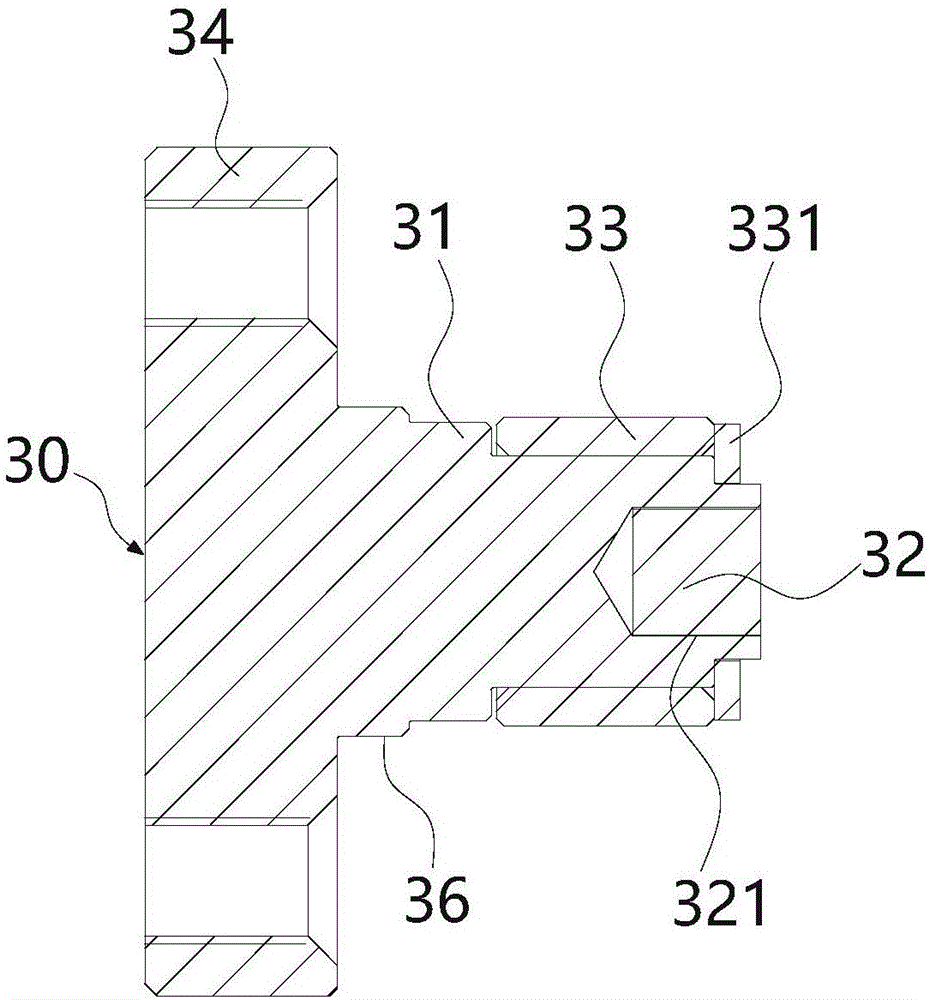
[0038] Such as Figure 1-4 As shown, a locking device according to an embodiment of the present invention generally includes a lock base 20 for providing a locking point, a lock shaft 30 for insertion into the lock base 20, and a lock for unlocking the lock shaft 30 after insertion. connecting rod 10.

[0039] This lock base 20 comprises lock body 25, and this lock body is rectangular, and the front of lock body 25 is provided with the lock groove 21 that is recessed to lock body 25 inside, and this lock base 20 also comprises dead bolt groove 22 and is installed in the lock. The dead bolt 24 in the tongue groove, and the dead bolt groove 22 is communicated with the lock groove 21, and the dead bolt 24 is movably contained in the dead bolt groove 22.

[0040] The lock shaft 30 includes a shaft seat 34 with a fixing hole, and a shaft rod 31 vertically arranged on the surface of the shaft seat 34 , the shaft rod is used for inserting into the lock slot 21 of the lock base 20 fo...


PUM


Abstract

The invention provides a locking device and an electric automobile. The locking device comprises lock bases, a lock connecting rod and lock shafts, wherein each lock base is used for providing a point to be locked and comprises a lock body; a lock groove which is concave toward the inner part of the corresponding lock body is arranged on one face of the corresponding lock body; each lock body is internally provided with a lock tongue groove and a lock tongue which is movably mounted in the lock tongue groove; the lock tongue grooves are communicated with the lock grooves; the lock connecting rod is movably connected with the lock bases through the lock tongues and comprises a rod part; the rod part drives the lock tongues to move in the lock tongue grooves under the action of an external force; each lock shaft comprises a shaft seat and a shaft rod; and the shaft rods are vertically arranged on the surfaces of the shaft seats, and the shaft rods are inserted into the lock grooves of the lock bases and are used for locking. According to the locking device and the electric automobile, the plurality of lock shafts, which are distributed at a side edge of a battery, are utilized and are inserted into the plurality of lock bases located on the electric automobile, so that the battery is fixed on the electric automobile; and the plurality of lock shafts can be automatically locked by the lock bases at the same time through utilizing the movement of the lock connecting rod, so that the installation efficiency and detachment efficiency of the battery are greatly improved.

Description

technical field [0001] The invention relates to the field of electric vehicles, in particular to a locking structure for locking a battery of an electric vehicle on the electric vehicle, and an electric vehicle using the locking device. Background technique [0002] The battery installation methods of existing electric vehicles are generally divided into fixed type and replaceable type, wherein the fixed type battery is generally fixed on the car, and the car is directly used as the charging object when charging. And replaceable battery generally adopts the mode of movable installation, and battery can be taken off at any time, to replace or charge, after changing or charging finishes, install on the car body again. [0003] The current battery replacement methods include manual and automatic operations. Regardless of the method, the battery is installed on the chassis of the electric vehicle. After installation, the battery needs to be locked on the vehicle body. Because th...

Claims


Application Information

Patent Timeline
Patent Type & Authority Applications(China)
IPC IPC(8): B60K1/04H01M50/249H01M50/264
CPCB60L53/80B60K1/04H01M50/264H01M50/249B60K2001/0455B60L50/64B60K2001/0472Y02T10/7072Y02T10/70B60Y2200/91Y02T90/12H01M2220/20
Inventor 张建平
Owner SHANGHAI DIANBA NEW ENERGY RESOURCES SCI & TECH
Learn More