Automobile charging robot
A technology for car charging and robotics, applied in the field of robotics, can solve the problems of slow operation, unable to meet the needs of charging positioning, high cost, etc., to achieve the effect of increasing efficiency, cheap cost and saving time
- Summary
- Abstract
- Description
- Claims
- Application Information
AI Technical Summary
Problems solved by technology
Method used
Image
Examples
Embodiment 1
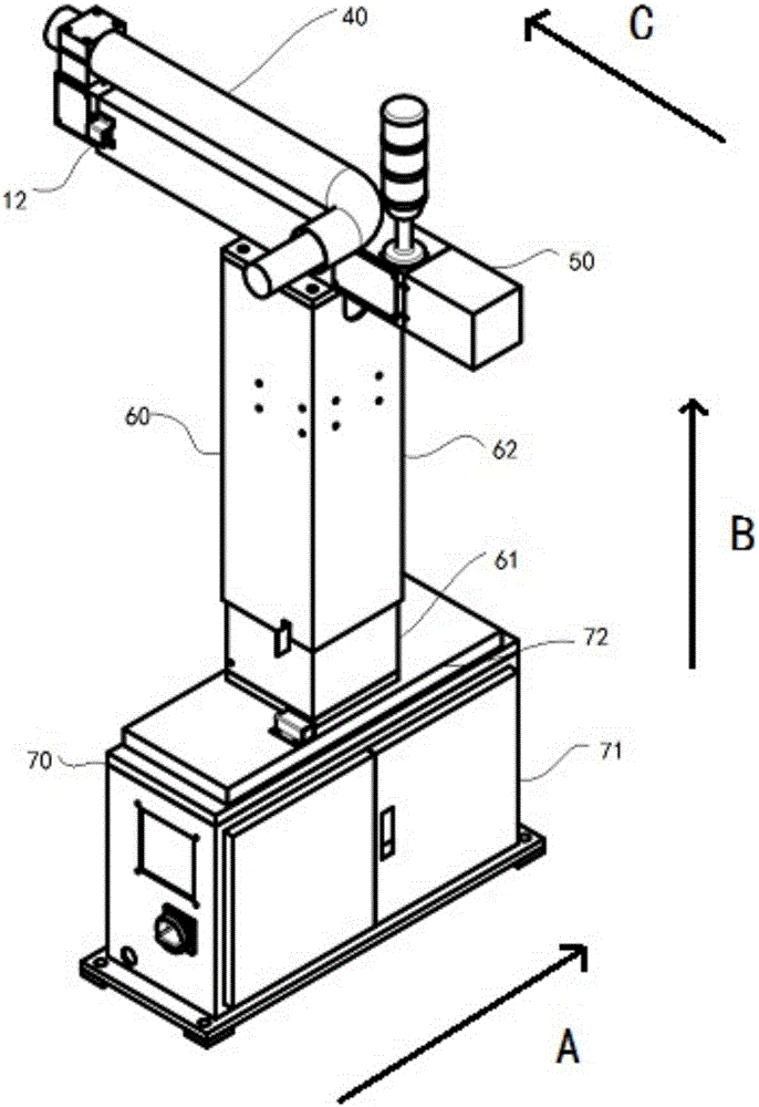
[0031] This embodiment provides a car charging robot, such as Figure 1-9 shown, including:
[0032] The charging connector 40, the displacement platform 30 for carrying the charging connector 40 and moving the charging connector 40, the induction device 10 for sensing the position of the charging interface 41 matched with the charging connector 40 on the car, and the displacement platform 30 and the displacement platform 30 respectively The sensing device 10 is connected to control the control system 20 in which the displacement platform 30 carries the charging connector 40 to move and dock with the charging interface 41 based on the sensing signal of the sensing device 10 .
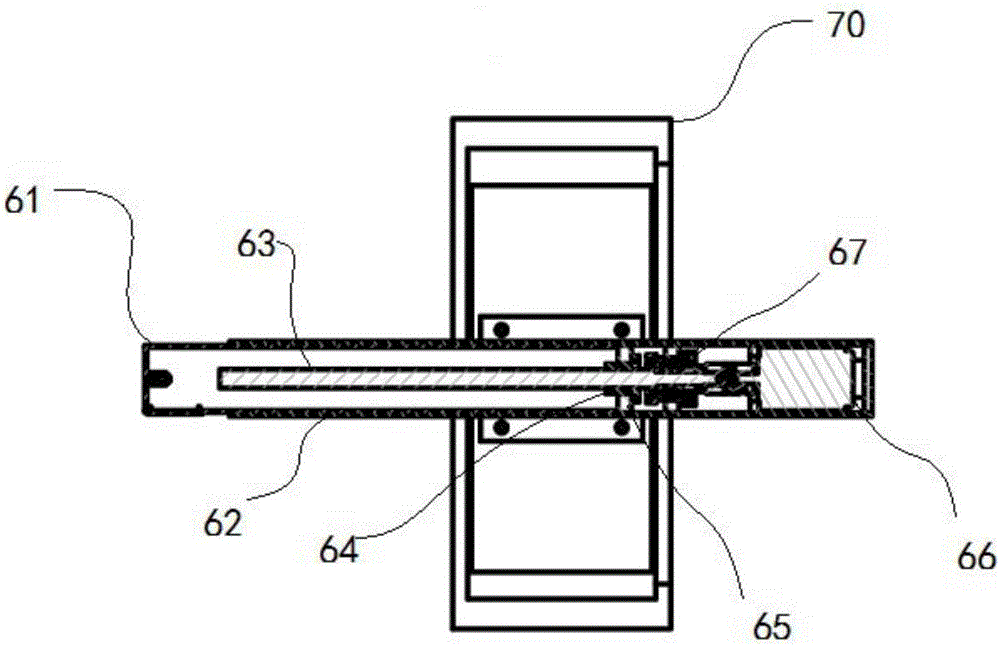
[0033] In this embodiment, the displacement platform 30 is an XYZ three-direction displacement platform, and the displacement platform 30 includes: a first-direction displacement mechanism 50, a second-direction displacement mechanism 60 and a third-direction displacement mechanism 70, the first-directi...
Embodiment 2
[0045] The difference between this embodiment and the above-mentioned embodiments is that the displacement table of the second displacement mechanism 60 is an inner sleeve 61, the displacement base is an outer sleeve 62, the guide rail 69 is fixed on the inner wall of the outer sleeve 62, and the movable part 68 One side is movably assembled with the guide rail 69, and the other side is fixed on the inner wall of the inner sleeve 61.
Embodiment 3
[0047] The difference between this embodiment and the above-mentioned embodiments is that the displacement platform of the first direction displacement mechanism 50 is the inner sleeve 61, the displacement base is the outer sleeve 62, and the connecting piece 65 is fixed between the nut 64 and the inner wall of the inner sleeve 61. Between, the inner sleeve 61 is used to carry the charging connector 40 .
PUM
 Abstract
Description
Claims
Application Information
 - R&D
- Intellectual Property
- Life Sciences
- Materials
- Tech Scout
- Unparalleled Data Quality
- Higher Quality Content
- 60% Fewer Hallucinations
Browse by: Latest US Patents, China's latest patents, Technical Efficacy Thesaurus, Application Domain, Technology Topic, Popular Technical Reports.
© 2025 PatSnap. All rights reserved.Legal|Privacy policy|Modern Slavery Act Transparency Statement|Sitemap|About US| Contact US: help@patsnap.com


