An in-orbit solar panel deployment device

A technology of solar panels and deployment mechanism, applied in the field of aviation solar panels, can solve the problems of inability to realize screw screwing, failure and scrapping of solar panels on-orbit deployment, inability to achieve on-orbit maintenance, etc. The effect of small network and simple product

Active Publication Date: 2019-01-08
SHANGHAI AEROSPACE SYST ENG INST
View PDF7 Cites 0 Cited by
  • Summary
  • Abstract
  • Description
  • Claims
  • Application Information

AI Technical Summary

Problems solved by technology

[0005] The purpose of the present invention is to provide an on-orbit solar panel deployment device to solve the technical problems in the prior art that the screw cannot be screwed, the on-orbit maintenance cannot be realized, and the solar panel can only be scrapped once there is an on-orbit deployment failure.

Method used


Image

  • An in-orbit solar panel deployment device

Examples


Embodiment Construction

[0019] The present invention will be described in detail below in conjunction with the accompanying drawings.

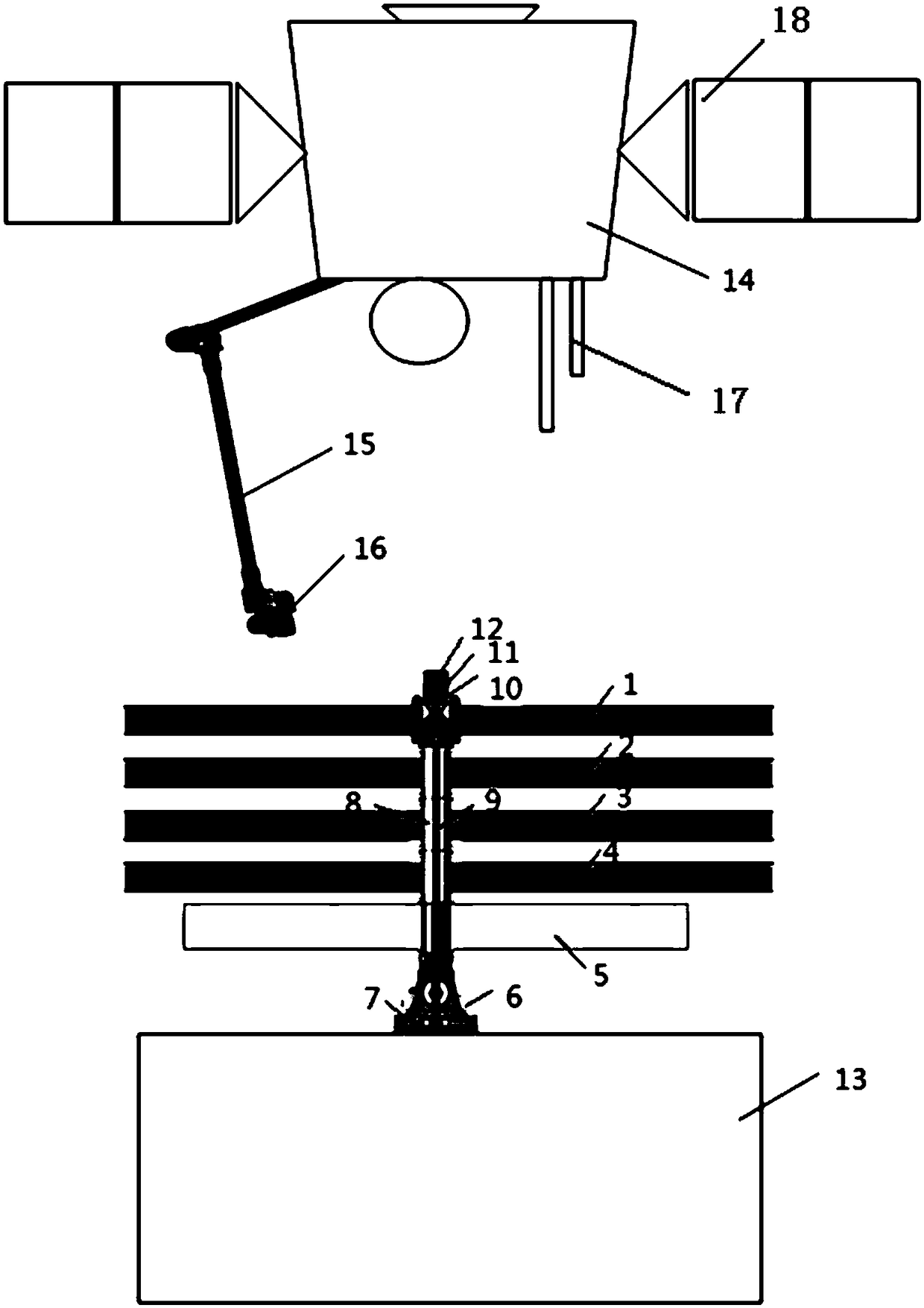
[0020] see figure 1 , an on-orbit solar panel deployment device, including an aircraft main system and an aircraft subsystem, wherein the aircraft main system includes a first body 13, a solar panel deployment mechanism, and the solar panel deployment mechanism is pressed and folded on the first body 13 When the solar panel deployment mechanism fails, the aircraft subsystem twists the solar panel deployment mechanism to deploy the solar panel deployment mechanism.

[0021] The compression base 7 is threadedly connected with the first main body 13, the cutter 6 is threaded with the compression base 7, the bottom end of the compression rod 9 is threaded with the compression base 7, the outer plate 1, the middle outer plate 21, and the middle inner plate 43 , the inner panel 4, and the connecting frame 5 are compressed and folded to the side of the first main body 13 t...


PUM


Abstract

The invention discloses an in-orbit solar panel unfolding device. The in-orbit solar panel unfolding device comprises an air-vehicle main system and an air vehicle subsystem. The air-vehicle main system comprises a first body and a solar panel unfolding mechanism, and the solar panel unfolding mechanism is tightly pressed and unfolded on the first body; when the solar panel unfolding mechanism fails during unfolding, the air vehicle subsystem is used for unscrewing the solar panel unfolding mechanism to unfold the solar panel unfolding mechanism. According to the in-orbit solar panel unfolding device, a screw, a nut, a locking nut and a pressed rod of the air-vehicle main system are unscrewed and disassembled through an unscrewing tool, the pressed rod is unscrewed from a pressing base, the function of unfolding a solar panel in an assisted mode is achieved accordingly, the in-orbit fault that as a cutter fails, unfolding cannot be achieved, and power supplying of a satellite cannot be achieved is overcome, and the in-orbit fine repairing demand of an air vehicle is guaranteed.

Description

technical field [0001] The invention relates to the field of aviation solar panels, in particular to an on-orbit solar panel deployment device. Background technique [0002] At present, aircraft such as satellites or space stations usually use solar panels for energy supply. In order to meet the envelope requirements of the launch vehicle, several sets of compression and release mechanisms are generally used to fold and compress the panels on the satellite body before launch. However, there are The following defects: [0003] The compression and release mechanism has high reliability requirements. Once the cutter fails or the pyrotechnic circuit fails to detonate the cutter, the solar panels cannot be deployed normally, and power supply to the on-satellite equipment cannot be provided, eventually leading to the scrapping of the entire satellite. [0004] At present, conventional satellites do not have on-orbit fine maintenance functions, and cannot perform actions such as s...

Claims


Application Information

Patent Timeline
Patent Type & Authority Patents(China)
IPC IPC(8): B64G1/44
CPCB64G1/44
Inventor 何玲康志宇赵真肖余之刘鹏宇
Owner SHANGHAI AEROSPACE SYST ENG INST
Why Eureka
Try Eureka