Coil pipe fan structure

A coil fan and fan technology, applied in the direction of mechanical equipment, machine/engine, liquid fuel engine, etc., can solve the problems of noise generation, affecting fan efficiency, unreasonable parameter ratio design, etc., to reduce noise and improve operating efficiency Effect

Active Publication Date: 2017-02-22
ZHONGSHAN BROAD OCEAN
View PDF5 Cites 11 Cited by
  • Summary
  • Abstract
  • Description
  • Claims
  • Application Information

AI Technical Summary

Problems solved by technology

[0005] Due to the unreasonable design of the parameter ratio between the volute 101 and the wind wheel 102, ...

Method used


Image

  • Coil pipe fan structure
  • Coil pipe fan structure
  • Coil pipe fan structure

Examples


Embodiment Construction

[0037] The present invention will be described in further detail below through specific embodiments and in conjunction with the accompanying drawings.

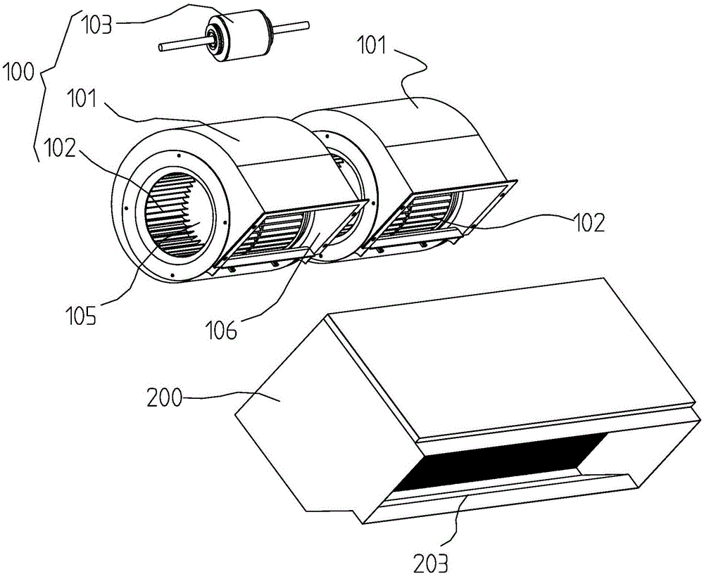
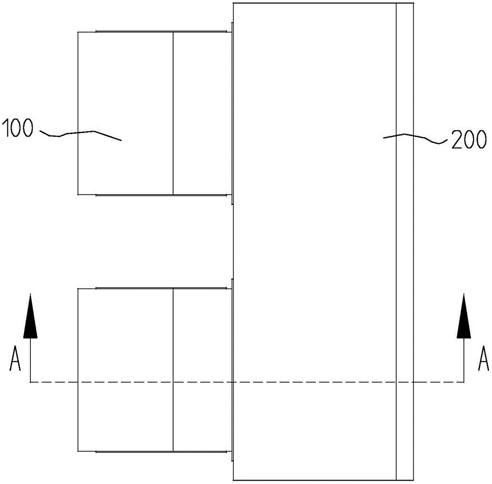
[0038] Such as Figure 4 to Figure 10 As shown, the present invention is a coil fan structure, including a blower 1, a fan box 2 and a heat exchanger 3, the blower 1 includes a volute 11, a wind wheel 12 and a motor 13, and the wind wheel 12 is installed on the volute Inside the first cavity 111 of the casing 11, the volute 11 is provided with a first air inlet 112 and a first air outlet 113, and the output shaft 131 of the motor 13 extends into the first cavity 111 and is connected with the wind wheel 12 for installation. The box body 2 is provided with a second cavity 21, one side of the fan box body 21 is provided with a second air inlet 22, the other side of the fan box body 2 is provided with a second air outlet 22, and the heat exchanger 3 is installed in the second cavity 21 And between the second air inlet 22 and the ...


PUM


Abstract

The invention discloses a coil pipe fan structure which comprises an air blower, a fan box and a heat exchanger. The air blower comprises a volute, an air wheel and a motor, the air wheel is mounted in a first cavity of the volute, and the volute is provided with a first air inlet and a first air outlet. An output shaft of the motor stretches into the first cavity to be connected with the air wheel in a mounted manner, the fan box is provided with a second cavity, a second air inlet is formed in one side of the fan box, and a second air outlet is formed in the other side of the fan box. The heat exchanger is mounted in the second cavity and located between the second air inlet and the second air outlet, a volute tongue part of the first air outlet of the volute is connected with an inclined plate, the higher end of the inclined plate is connected with a volute tongue of the volute air outlet, and the lower end of the inclined plate obliquely extends downwards in the direction close to the heat exchanger. A static pressure reset device is arranged on the first air outlet of the volute, on the basis of the static pressure reset device, volute parameter setting meets the following condition that 1.65>=2*b2/D2>=1.45, the operating efficiency of the motor and the operating efficiency of the fan can be effectively improved, and noise of the fan can be reduced.

Description

[0001] Technical field: [0002] The invention relates to a coil fan structure. [0003] Background technique: [0004] Existing coil fan structure such as figure 1 , figure 2 , image 3 As shown, it includes a blower 100, a fan box 200 and a heat exchanger 300. The blower 100 includes a volute 101, a wind wheel 102 and a motor 103. The wind wheel 102 is installed in the first cavity 104 of the volute 101, The volute 101 is provided with a first air inlet 105 and a first air outlet 106, the first air inlet 105 and the first air outlet 106 communicate with the first cavity 104, and the output shaft of the motor 103 extends into the inside of the first cavity 104 to communicate with the first cavity 104. The wind wheels 102 are connected and installed, the fan box body 200 is provided with a second cavity 201, the side of the fan box body 200 is provided with a second air inlet 202, the other side of the fan box body 200 is provided with a second air outlet port 203, and the ...

Claims


Application Information

Patent Timeline
IPC IPC(8): F04D25/08F04D29/42F04D29/28F04D29/66
CPCF04D25/08F04D29/281F04D29/4226F04D29/664
Inventor 林炎虎黎健辉
Owner ZHONGSHAN BROAD OCEAN
Why Eureka
Try Eureka