
Hydraulic valve control device

A control device, hydraulic valve technology, applied in valve device, valve operation/release device, valve details, etc., can solve problems such as hydraulic valve damage, unstable working current of electromagnetic hydraulic valve, etc.

Inactive Publication Date: 2017-02-22
HEFEI XIELI HYDRAULIC TECH CO LTD
View PDF5 Cites 0 Cited by
  • Summary
  • Abstract
  • Description
  • Claims
  • Application Information

AI Technical Summary

Problems solved by technology

[0004] The invention proposes a hydraulic valve control device, which solves the problem in the prior art that the working current of the electromagnetic hydraulic valve is unstable and easily causes damage to the hydraulic valve

Method used


Image

  • Hydraulic valve control device
  • Hydraulic valve control device

Examples


Embodiment Construction

[0019] The following will clearly and completely describe the technical solutions in the embodiments of the present invention with reference to the accompanying drawings in the embodiments of the present invention. Obviously, the described embodiments are only some, not all, embodiments of the present invention. Based on the embodiments of the present invention, all other embodiments obtained by persons of ordinary skill in the art without creative efforts fall within the protection scope of the present invention.

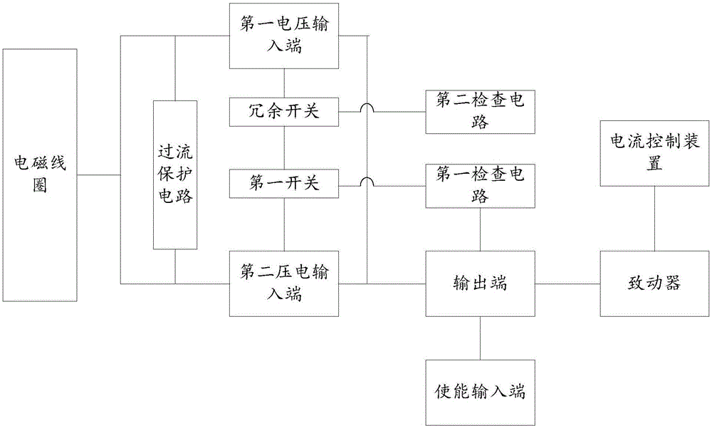
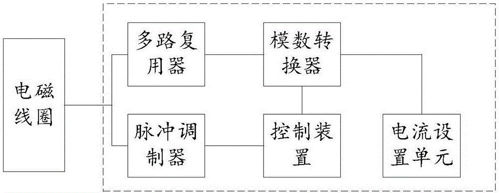
[0020] Such as figure 1 As shown, the hydraulic valve control device of this embodiment, the hydraulic valve control device, includes a first voltage input terminal and at least one actuator for driving the electromagnetic coil; the output terminal is used to output the driving current of the actuator, and the The output terminal is provided with a second voltage input terminal; a first switch is provided between the first voltage input terminal and the second volt...


PUM


Abstract

The invention provides a hydraulic valve control device. The hydraulic valve control device comprises a first voltage input end, at least one actuator for driving an electromagnetic coil, an output end which is used for outputting driving current of the actuator and provided with a second voltage input end, and checking circuits which are used for checking whether a first switch works normally when the output end is located in a connection position, and turning on the first switch when the output end is located in a disconnection position, wherein the first switch is arranged between the first voltage input end and the second voltage input end; the output end is provided with an enabling input end which is used for switching the output end between the connection position and the disconnection position. Through the hydraulic valve control device, stable operation of a hydraulic valve can be protected, damage of the hydraulic valve due to failures is avoided, and the service life of the hydraulic valve is prolonged.

Description

technical field [0001] The invention belongs to the technical field of engineering machinery, in particular to a hydraulic valve control device. Background technique [0002] At present, the slide valve mechanism is the most widely used structural form in various hydraulic valves. The slide valve is composed of three main parts: the valve body, the valve core and the valve cavity. By changing the position of the valve core in the valve body cavity, the slide valve The valve can realize the change and on-off of fluid flow. In the working process of the electromagnetic hydraulic valve, it is necessary to use current to control the advancement of the electromagnetic coil. The magnitude of the current will affect the operation of the hydraulic valve, and when the current is too large, it will cause damage to the hydraulic valve. Cause the work of the hydraulic valve is not in place. [0003] Therefore, there is an urgent need for a hydraulic valve control device that can prote...

Claims


Application Information

Patent Timeline
Patent Type & Authority Applications(China)
IPC IPC(8): F16K31/06
CPCF16K31/0675
Inventor 张勇邓继周赵岗
Owner HEFEI XIELI HYDRAULIC TECH CO LTD
Learn More