
Clip connection structure and fresh air ventilator

A connection structure, a new fan technology, applied in the electrical field, can solve the problems of inconvenient disassembly and installation, damage to the panel and the base of the fan unit, etc.

Active Publication Date: 2017-02-22
GREE ELECTRIC APPLIANCES INC
View PDF5 Cites 6 Cited by
  • Summary
  • Abstract
  • Description
  • Claims
  • Application Information

AI Technical Summary

Problems solved by technology

[0003] At present, the clamping method between the panel and the upper cover of the fan unit base is to directly connect the two together, so that when the two are disassembled and installed, it is necessary to align the front panel and the fan unit base. The relative position makes it inconvenient to disassemble and install. In the process of frequent disassembly and installation, it is easy to cause damage to the fastened parts on the panel and the base of the fan unit.

Method used


Image

  • Clip connection structure and fresh air ventilator
  • Clip connection structure and fresh air ventilator
  • Clip connection structure and fresh air ventilator

Examples


Embodiment 1

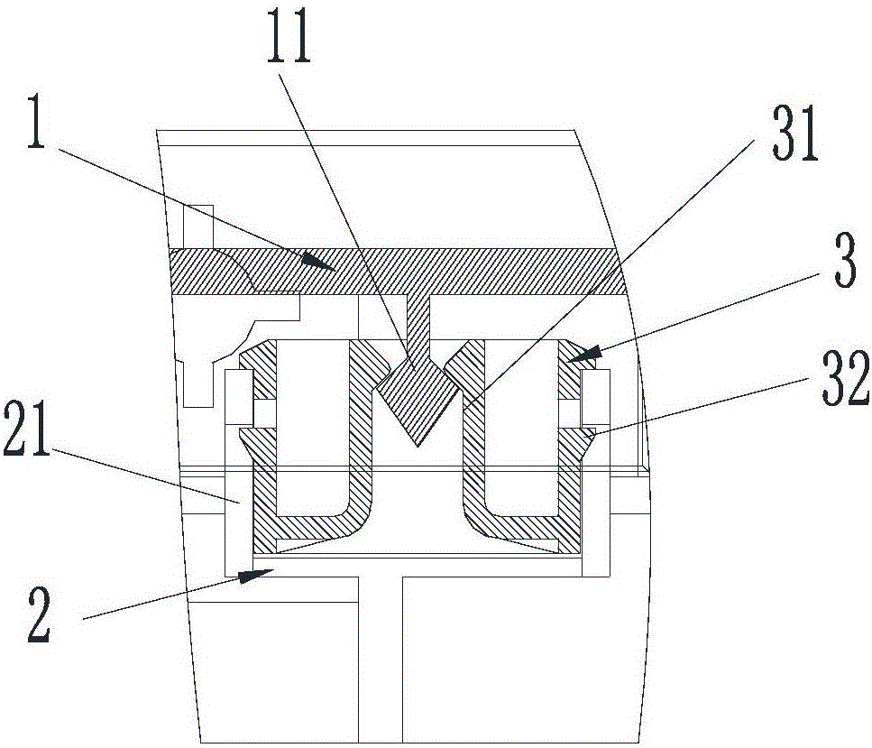
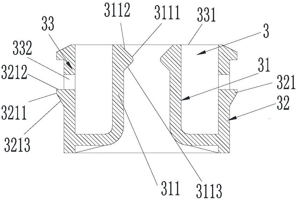
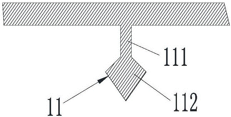
[0037] Such as figure 1 As shown, a buckle connection structure includes: a first part 1, a second part 2 and a buckle 3; the buckle 3 includes a first buckle part 31 and a second buckle part 32, and the buckle 3 passes through the first The clamping portion 31 is clamped on the first component 1 , and is clamped on the second component 2 through the second clamping portion 32 to connect the first component 1 and the second component 2 .

[0038] During the connection process between the first component 1 and the second component 2 , the buckle 3 can be clamped on the second component 2 through the second clamping portion 32 first, and then the first component 1 can be clamped on the buckle 3 . The disassembly process is just the opposite, so that during the installation and disassembly process of the first part 1 and the second part 2, the alignment requirements for the first part 1 and the second part 2 are lower, which improves the disassembly and assembly between the two p...

Embodiment 2

[0052] Such as Figure 5 As shown, a new fan includes the snap-fit ​​connection structure described in Embodiment 1, wherein the first component is the panel 4 of the fan, that is to say, the third snapping part is arranged on the panel 4 . The second part is the loam cake 5 (being the loam cake of fan base) of blower fan, that is to say as Figure 6 As shown, the fourth engaging portion 21 is disposed on the upper cover 5 .

[0053] In actual use, the number of snaps 3 is more than two; the number of the third snapping parts on the panel and the number of the fourth snapping parts 21 on the upper cover 5 are equal to the number of snaps, and respectively One-to-one connection through buckles.

[0054] During installation, the buckle 3 can be installed in one-to-one correspondence with the fourth buckle 21 on the upper cover 5, and then the third buckle on the panel 4 and the corresponding buckle can be installed together to realize the panel 4 The specific installation met...


PUM


Abstract

The invention discloses a clip connection structure and a fresh air ventilator. The clip connection structure comprises a first component, a second component and a clip, wherein the clip comprises a first clamping part and a second clamping part; and the clip is clamped on the first component through the first clamping part, and is clamped on the second component through the second clamping part, so as to connect the first component with the second component. The clip connection structure and the fresh air ventilator which are disclosed by the invention enable the working of detachment and installation between the first component and the second component to be more convenient and faster, and then avoid damage of the first component and the second component during a process of frequent detachment and installation.

Description

technical field [0001] The invention relates to the technical field of electrical appliances, in particular to a buckle connection structure and a fresh fan. Background technique [0002] Existing fresh air fan products involve periodic replacement of internal components, such as cleaning and replacement of filter screens and total heat exchange cores, so it is necessary to periodically disassemble the panel from the upper cover of the fan unit base and take out the relevant components for disposal After completion, install the panel on the upper cover of the fan unit base. In order to facilitate the disassembly and installation of the panel, the panel and the upper cover of the fan unit base are fixedly connected by clamping. From the service cycle of the fan unit, the number of operations to remove the panel is correspondingly frequent. [0003] At present, the clamping method between the panel and the upper cover of the fan unit base is to directly connect the two togeth...

Claims


Application Information

Patent Timeline
IPC IPC(8): F24F13/32
CPCF24F13/32
Inventor 杨力刘煜詹朝永苏炳珲符美军刘莹
Owner GREE ELECTRIC APPLIANCES INC
Learn More