Bipod capable of achieving tube back end compression ejection

A back-end compression, two-legged technology, applied in the field of bipods, can solve the problems affecting the appearance and the stability of the foot ejection, affecting the shooting accuracy, damage to the end face of the tube, etc., achieving rapid deployment, reducing shaking gaps, and locking firmly Effect

Inactive Publication Date: 2017-02-22
陈小鸣
View PDF5 Cites 3 Cited by
  • Summary
  • Abstract
  • Description
  • Claims
  • Application Information

AI Technical Summary

Problems solved by technology

[0003] At present, the same type of tripod seat on the market is injected with an external spring at the front end of the foot. The product has the following defects: the spring is exposed and installed on the front end of the tube. When the spring is compressed, the end surface of the tube is damaged, which affects the appearance and the stability of the foot ejection.
In addition, the inner and outer tube structures of the same type on the market are not equipped with a stabilizing device, and when locked, they vibrate due to the excessive gap, which directly affects the shooting accuracy; while the inner and outer tube structures with built-in tension springs, When deploying and shooting, you need to hold the outer tube with one hand, and pull out the inner tube with the other hand. After pulling out one inner tube, you can repeatedly pull out the other inner tube. Make it convenient and fast

Method used


Image

  • Bipod capable of achieving tube back end compression ejection
  • Bipod capable of achieving tube back end compression ejection
  • Bipod capable of achieving tube back end compression ejection

Examples


Embodiment Construction

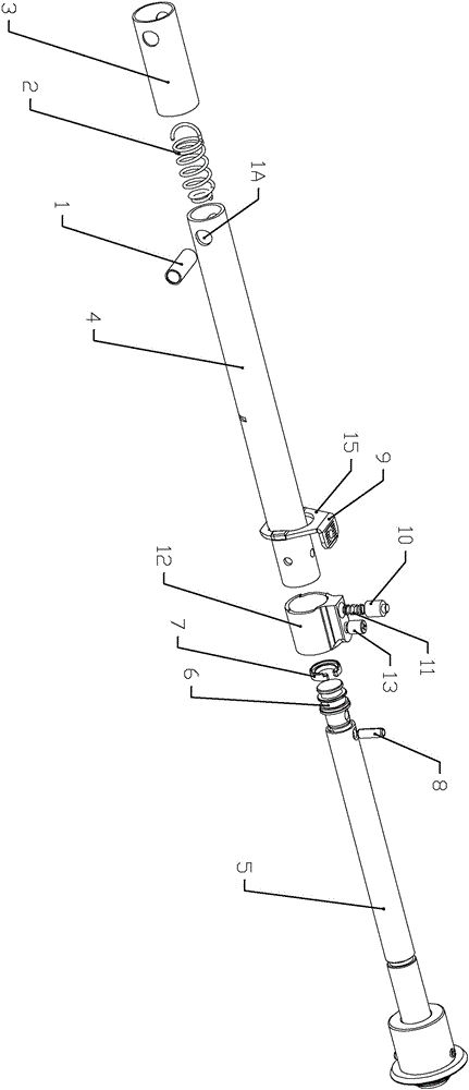
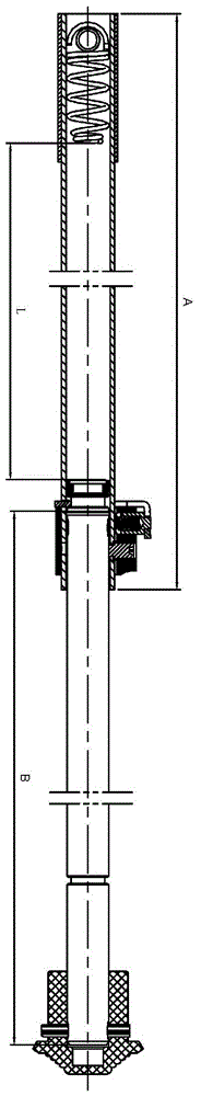
[0029] Figure 1-10 It is an exemplary embodiment of the bipod that is compressed and injected from the rear end of the tube according to the present invention, and the specific structural details in the individual drawings are only used as exemplary descriptions to explain the technical solutions of the present invention, and are not intended to limit the present invention. Wherein, the various embodiments according to the present invention have common structural parts, and for the sake of simplicity, different embodiments may be described by referring to the same drawing.

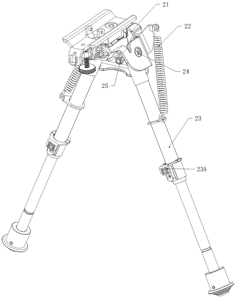
[0030] Such as figure 1 Shown is a perspective view of an embodiment of the tripod according to the present invention, and the tripod includes: a bracket assembly 21 ;

[0031] Specifically, the tripod further includes: pin return springs 22 , hexagon socket head screws 24 , and hexagon socket nuts 25 . The hexagon socket head cap screws 24 are used to connect the inner pin assembly 23 and the bracket a...


PUM


Abstract

The invention relates to a bipod capable of achieving tube back end compression ejection. The bipod includes a support assembly; and at least two ejection inner pin assemblies hinged to the lower part of the support assembly. Each ejection inner pin assembly includes an outer tube for holding a compression spring and an inner pin; an inner pin having a first shape in which the inner pin completely retracts to the outer tube and a second shape in which the inner pin is completely ejected out of the outer tube; a compression spring which is positioned in the outer tube and is pressed against one end, facing the outer tube, of the inner pin; and a switch mechanism for releasing or clamping the inner pin. During use, the support assembly is arranged on an object to be supported, the inner pin assemblies are unfolded, and when the switch mechanism is energized, the inner pins are released from the first shape and ejected to the second shape under the action of the spring force of the compression springs. The inner pin can retract from the second shape to the first shape by a third shape partially retracting to the outer tube. The bipod can achieve rapid telescopic adjustment of a rifle, and can be used in various terrains.

Description

technical field [0001] The invention relates to a bipod, in particular to a bipod whose rear end is compressed and injected. Background technique [0002] When shooting firearms for sports competition, in order to increase the shooting stability, a tripod device is generally used for support. Present sports competition firearms, such as competition rifles, its tripod is generally a herringbone bipod. Two expandable tripod rods are installed at the lower end of the tripod seat. When in use, install the tripod joint on the rifle on the tripod seat, and then unfold the tripod rod to realize support and facilitate shooting. [0003] At present, the same type of tripod seat on the market uses an external spring at the front end of the foot to compress and inject the product. The product has the following defects: the spring is exposed and installed on the front end of the tube. In addition, because the inner and outer tube structures of the same type on the market do not have ...

Claims


Application Information

Patent Timeline
Patent Type & Authority Applications(China)
IPC IPC(8): F41A23/10
CPCF41A23/10
Inventor 陈小鸣
Owner 陈小鸣
Why Eureka
Try Eureka