
Infrared charging detection device and compensation method based on automatic temperature and humidity compensation

A technology of automatic compensation and live detection, applied in measurement devices, radiation pyrometry, special recording/indicating devices, etc., can solve problems such as error in detection results, achieve high temperature measurement accuracy, meet accuracy requirements, and solve errors in detection results larger effect

Active Publication Date: 2019-07-05
PDSTARS ELECTRIC CO LTD
View PDF3 Cites 0 Cited by
  • Summary
  • Abstract
  • Description
  • Claims
  • Application Information

AI Technical Summary

Problems solved by technology

[0003] In view of the defects in the prior art, the object of the present invention is to provide an infrared electrification detection device based on automatic temperature and humidity compensation and its compensation method, which solves the problem that the relative humidity of rainy and foggy weather, which is faced by power grid equipment, causes the detection results to be relatively high. The problem of large errors, the temperature measurement accuracy is still high in the case of high relative humidity, which can well meet the accuracy requirements of on-site infrared live detection

Method used

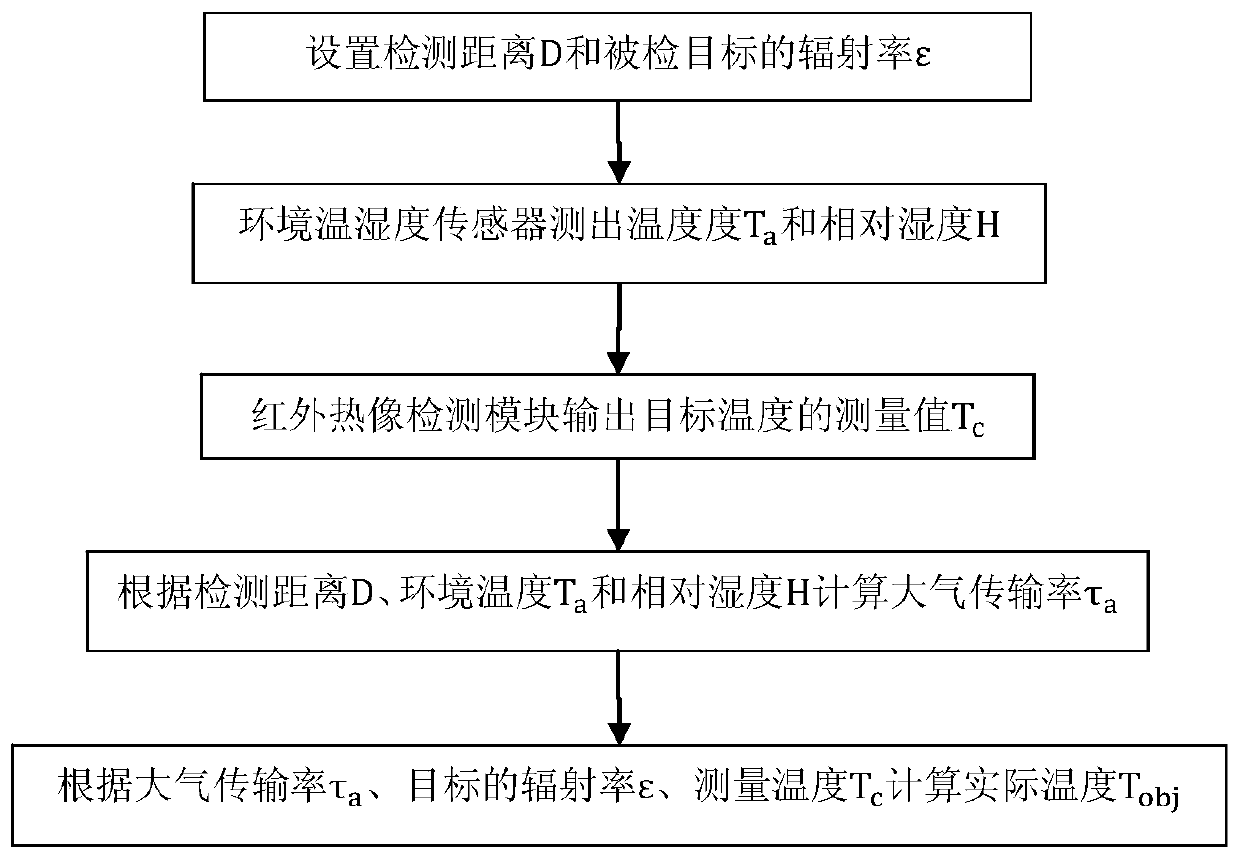
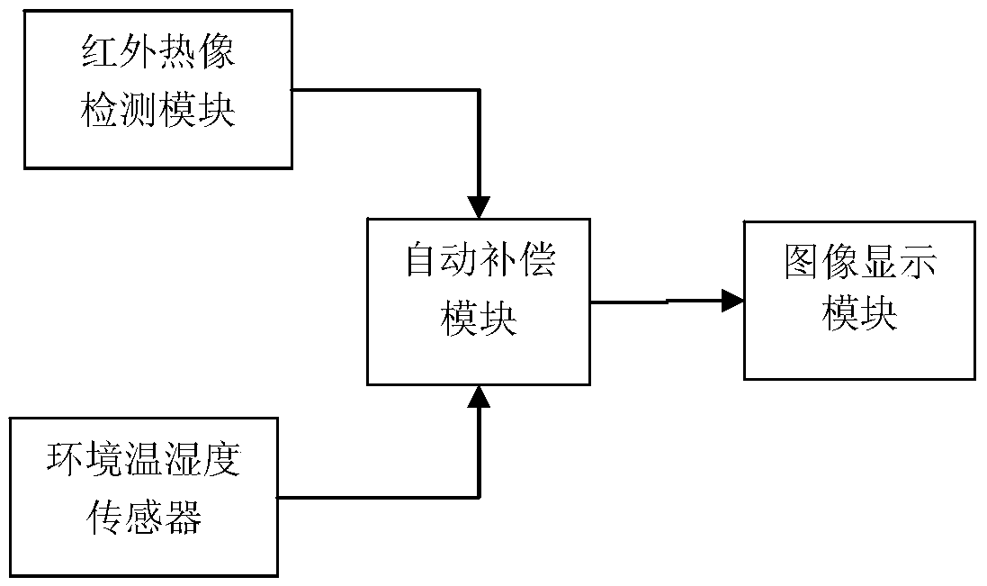

Image

  • Infrared charging detection device and compensation method based on automatic temperature and humidity compensation
  • Infrared charging detection device and compensation method based on automatic temperature and humidity compensation
  • Infrared charging detection device and compensation method based on automatic temperature and humidity compensation

Examples


Embodiment Construction

[0043] The present invention will be described in detail below in conjunction with specific embodiments. The following examples will help those skilled in the art to further understand the present invention, but do not limit the present invention in any form. It should be noted that those skilled in the art can make several modifications and improvements without departing from the concept of the present invention. These all belong to the protection scope of the present invention.

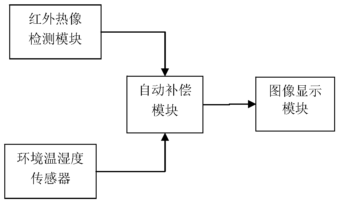
[0044] Such as figure 1As shown, an infrared charging detection device based on automatic temperature and humidity compensation provided by the present invention includes an ambient temperature and humidity sensor, an infrared thermal image detection module, an automatic compensation module, and an image display module. Among them, the ambient temperature and humidity sensor is connected with the automatic compensation module, which is used to detect the ambient temperature and relative humidity d...


PUM


Abstract

The invention provides an infrared live line detector based on temperature and humidity automatic compensation, and a compensation method thereof. The infrared live line detector based on temperature and humidity automatic compensation includes an environment temperature and humidity sensor, an infrared thermal imaging detection module, an automatic compensation module and an image display module, wherein the environment temperature and humidity sensor is used for detecting the environment temperature and the relative humidity; the infrared thermal imaging detection module is used for operating infrared temperature detection on the surface of an object in the field range; the automatic compensation module is used for automatically compensating the detection result of the infrared thermal imaging detection module according to the environment temperature and humidity; and the image display module displays the temperature values after compensation of the surface of the object in the field range by means of different colors. The infrared live line detector based on temperature and humidity automatic compensation, and the compensation method thereof can solve the problem that infrared live line detection of power grid equipment is high in the error of detection results because of the high relative humidity in the rainy and foggy weather, and can maintain high temperature detecting accuracy when the relative humidity is high and can preferably satisfy the accuracy requirement for infrared live line detection on site.

Description

technical field [0001] The invention relates to an infrared electrification detection device based on automatic temperature and humidity compensation and a compensation method thereof, which belongs to the technical field of electrical equipment electrification detection, and is a patrol inspection device and an infrared detector for accurately measuring the temperature distribution of the outer surface of electrical equipment in a field environment. temperature compensation method. Background technique [0002] Domestic power equipment has carried out condition-based maintenance with infrared thermal image live detection as an important technical means, and achieved good results. Overheating caused by equipment defects can be effectively found and the defects can be eliminated in time to avoid the occurrence of malignant failures of power equipment. However, there is a common problem with infrared thermal image detection devices for power equipment at present. Since infrare...

Claims


Application Information

Patent Timeline
Patent Type & Authority Patents(China)
IPC IPC(8): G01J5/00G01D3/036
CPCG01D3/036G01J5/00
Inventor 黄成军郭灿新欧阳三元宋方张克勤
Owner PDSTARS ELECTRIC CO LTD
Learn More