High-precision contact thermal resistance measuring device under vacuum condition

A technology of contact thermal resistance and vacuum conditions, applied in the field of high-precision contact thermal resistance measurement devices, to achieve the effect of improving measurement accuracy

Inactive Publication Date: 2020-03-27
NANJING UNIV OF TECH +1
View PDF7 Cites 0 Cited by
  • Summary
  • Abstract
  • Description
  • Claims
  • Application Information

AI Technical Summary

Problems solved by technology

[0003] The purpose of the present invention is to provide a high-precision contact thermal resistance measurement device under vacuum conditions to solve the problem of arbitrarily switching the heat source and cold source when the test device is not disassembled, and to eliminate the influence of gravity during the stress loading process. Loading and unloading and overcoming the effect of convective heat transfer on thermal contact resistance

Method used


Image

  • High-precision contact thermal resistance measuring device under vacuum condition
  • High-precision contact thermal resistance measuring device under vacuum condition
  • High-precision contact thermal resistance measuring device under vacuum condition

Examples


Embodiment Construction

[0015] The present invention will be further described below in conjunction with accompanying drawing.

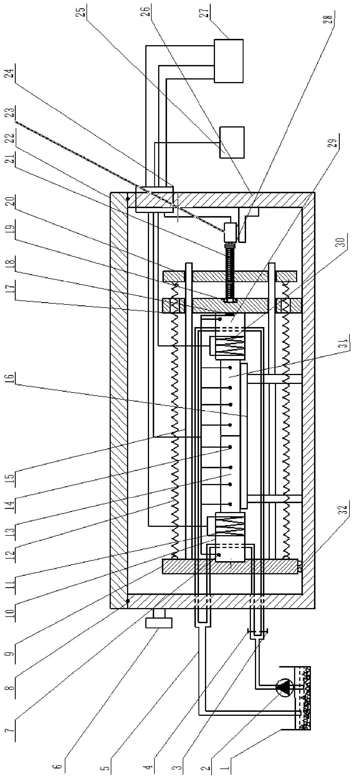
[0016] Such as figure 1 , a high-precision contact thermal resistance measurement device under vacuum conditions, which includes a vacuum chamber, a left moving plate 9, a spring 12, a guide rod 15, a left temperature control block 10, a right temperature control block 29, and a first DUT 13. The second DUT 31, the DUT support frame 16, the right fixed plate 17 and the right moving plate 20, the vacuum chamber includes the vacuum lower cavity 26 and the vacuum cavity upper cover 22, the left moving plate 9, the spring 12. Guide rod 15, left temperature control block 10, right temperature control block 29, first DUT 13, second DUT 31, DUT support frame 16, right fixed plate 17, right moving plate 20 They are all located inside the vacuum chamber, the DUT supporting frame 16 is fixed at the bottom of the cavity under vacuum, and the first DUT 13 and the second DUT 31 are pla...


PUM


Abstract

The invention discloses a high-precision contact thermal resistance measuring device under a vacuum condition. The contact thermal resistance measuring device comprises a vacuum cavity, a left movingplate (9), a spring (12), a guide rod (15), a left side temperature control block (10), a right side temperature control block (29), a first tested piece (13), a second tested piece (31), a tested piece support frame (16), a right fixed plate (17) and a right moving plate (20). According to the invention, the problem of large test result error caused by discontinuous stress loading / unloading, single heat flow direction, various test error sources and the like in the contact thermal resistance experiment device at the present stage is solved. The servo motor drives the lead screw to rotate so as to drive the spring to be stretched / compressed, stress loading / unloading is carried out, and the stress loading / unloading accuracy is guaranteed through the pressure sensor. The test is carried outin a vacuum environment, and the influence of convective heat transfer on the test result is overcome. The device is suitable for detecting the contact thermal resistance.

Description

technical field [0001] The invention relates to the field of contact thermal resistance measurement, in particular to a high-precision contact thermal resistance measurement device under vacuum conditions Background technique [0002] Observing two contact surfaces on a microscopic scale, two non-completely smooth contact surfaces are usually part of the crest contact, and there is an air gap between the crests. The two materials transfer heat in the form of heat conduction, so there is transfer resistance, that is, contact thermal resistance. In precision contact experiments, its existence cannot be ignored. The contact thermal resistance of the two tested parts will be comprehensively affected by factors such as stress, temperature, surface roughness, and heat flow direction. At present, the contact thermal resistance vacuum test device can only achieve one-sided temperature control, and the cold source and heat source are fixed. At the same time, the stress Loading / unloa...

Claims


Application Information

Patent Timeline
Patent Type & Authority Applications(China)
IPC IPC(8): G01N25/20
CPCG01N25/20
Inventor 孙付仲张小雨洪荣晶王华张浩
Owner NANJING UNIV OF TECH
Why Eureka
Try Eureka