
Position determination method and apparatus

A scanning direction, first-time technology, applied in the field of optical tracking, can solve problems such as large delay, small tracking range, and difficulty in implementation

Inactive Publication Date: 2017-02-22
HISENSE BROADBAND MULTIMEDIA TECH
View PDF5 Cites 2 Cited by
  • Summary
  • Abstract
  • Description
  • Claims
  • Application Information

AI Technical Summary

Problems solved by technology

The characteristic of optical tracking technology is that it can fully reflect the movement of objects and has high precision; the disadvantage is that it is difficult to realize, and the tracking range is small and the delay is large

Method used

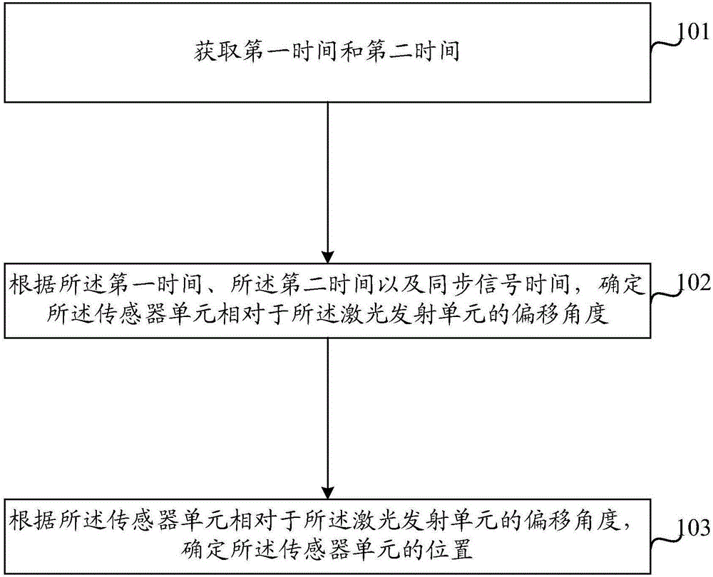
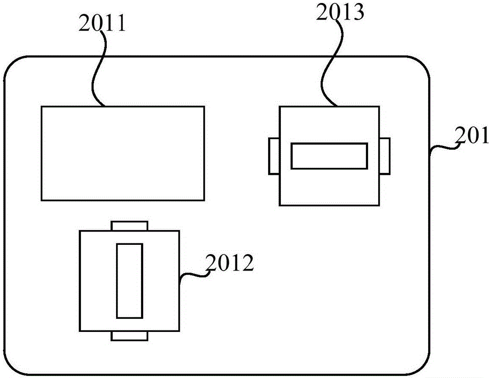
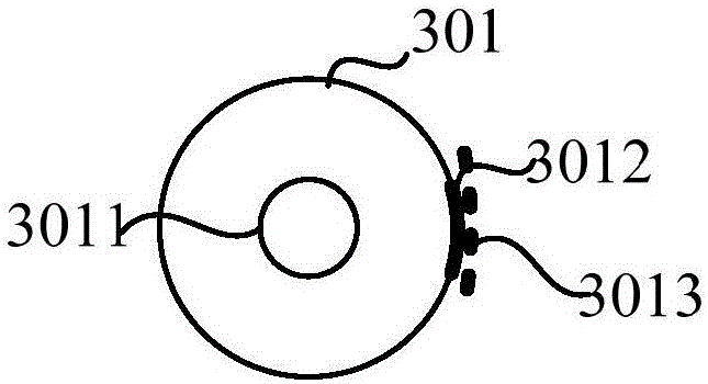

Image

  • Position determination method and apparatus
  • Position determination method and apparatus
  • Position determination method and apparatus

Examples


Embodiment Construction

[0020] In order to make the purpose, technical solutions and advantages of the present invention clearer, the present invention will be further described in detail below in conjunction with the accompanying drawings. Obviously, the described embodiments are only some of the embodiments of the present invention, rather than all of them. Based on the embodiments of the present invention, all other embodiments obtained by persons of ordinary skill in the art without making creative efforts belong to the protection scope of the present invention.

[0021] For the convenience of description, in the embodiment of the present invention, the sensor unit is used to represent the light receiving unit, and the laser emitting unit is used to represent the light emitting unit. The embodiment of the present invention is only an example, and the light receiving unit and the light emitting unit are not specifically limited. Other Both arrangements or devices for light reception and light emiss...


PUM


Abstract

The present invention discloses a position determination method and apparatus. The method includes the following steps that: a first time and a second time are acquired, wherein the first time is a time when a light receiving unit receives polarized light in a first scanning direction which is emitted by a light emitting unit, and the second time is a time when the light receiving unit receives polarized light in a second scanning direction which is emitted by the light emitting unit; the deviation angle of the light receiving unit relative to the light emitting unit is determined according to the first time, the second time and a synchronization signal time; and the position of the light receiving unit is determined based on the deviation angle of the light receiving unit relative to the light emitting unit. Since the light emitting unit can emit the polarized light in different scanning directions, the polarized light in the first scanning direction and the polarized light in the second scanning direction which are received by the light receiving unit in the same time period will not be mixed, and therefore, the speed of the determination of the position of a target object can be effectively improved, and system delay is reduced.

Description

technical field [0001] Embodiments of the present invention relate to the technical field of optical tracking, and in particular, to a method and device for determining a position. Background technique [0002] The main purpose of position determination and motion tracking technology is to track and feed back the position and motion changes of the target in real time, and obtain the three-dimensional space positioning of the target and its motion parameters. At present, inertial tracking technology and optical tracking technology are commonly used in the field of human-computer interaction. [0003] Inertial tracking technology, by setting an inertial measurement unit on the target, measuring data such as acceleration and angular velocity, and using mathematical tools to solve the motion of the target. The advantages are simple implementation and strong anti-interference. The disadvantage is that the motion characteristics of the tracked target cannot be obtained comprehen...

Claims


Application Information

Patent Timeline
IPC IPC(8): G01S5/16
CPCG01S5/16
Inventor 王文明
Owner HISENSE BROADBAND MULTIMEDIA TECH
Learn More