A Speed ​​Control Method for Rlv Approach and Landing Section Based on the Idea of ​​Nominal Speed ​​Compensation

A nominal speed, speed control technology, applied in altitude or depth control, vehicle position/route/altitude control, control/regulation system, etc. Achieve the effect of improving control accuracy, reducing influence and improving stability

Active Publication Date: 2019-05-24
BEIJING INST OF CONTROL ENG
View PDF5 Cites 0 Cited by
  • Summary
  • Abstract
  • Description
  • Claims
  • Application Information

AI Technical Summary

Problems solved by technology

[0003] The return and reentry process of RLV must meet the constraints of dynamic pressure, heat flow and attitude, especially for the reentry end—the approach and landing segment—because the RLV must strictly meet the requirements of ground speed and pitch angle at the touchdown point. Otherwise, if the ground speed exceeds the upper limit that the landing gear can withstand, or the tail of the RLV touches the ground due to excessive pitch angle, the RLV will be damaged and the landing will fail
However, the wind has a significant impact on the landing process of the RLV: when there is a headwind, the aerodynamic resistance of the RLV is greater, which may cause the ground speed to decrease and the angle of attack to increase when it touches the ground. Restrictions cause tail scrape; when tailwinds are present, the airspeed of the RLV will be reduced as a result, possibly causing excessive ground speed at touchdown and damage to the landing gear axle
During the RLV landing process, appropriately increasing or decreasing the airspeed command according to the environment can improve the landing performance. At present, most RLV speed control methods are to make the airspeed of the RLV track the designed nominal airspeed. This method In the nominal situation where there is no wind field, the RLV can successfully land, but the adaptability to environmental changes is poor, and the airspeed command cannot be changed according to environmental changes

Method used


Image

  • A Speed ​​Control Method for Rlv Approach and Landing Section Based on the Idea of ​​Nominal Speed ​​Compensation
  • A Speed ​​Control Method for Rlv Approach and Landing Section Based on the Idea of ​​Nominal Speed ​​Compensation
  • A Speed ​​Control Method for Rlv Approach and Landing Section Based on the Idea of ​​Nominal Speed ​​Compensation

Examples


Embodiment

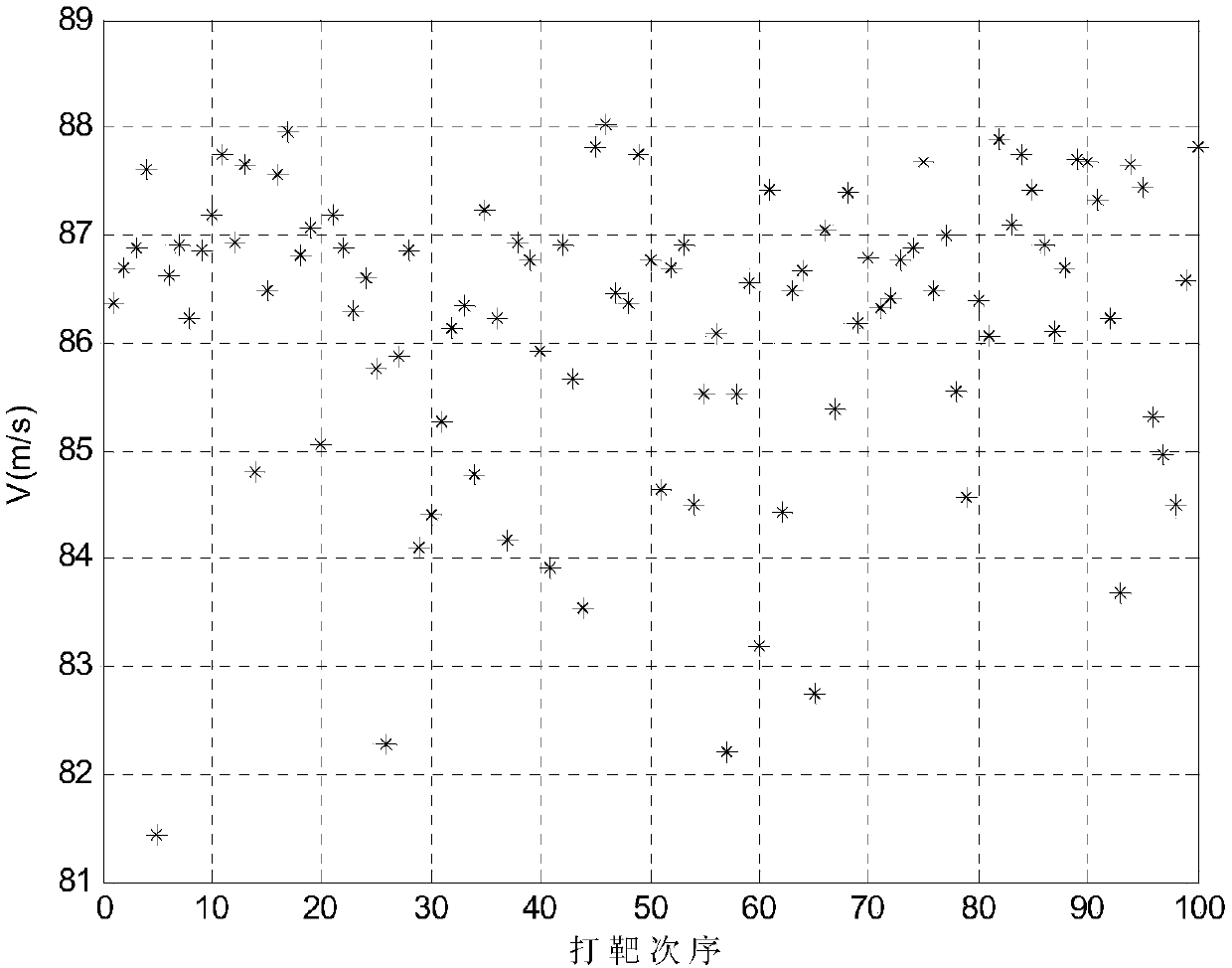
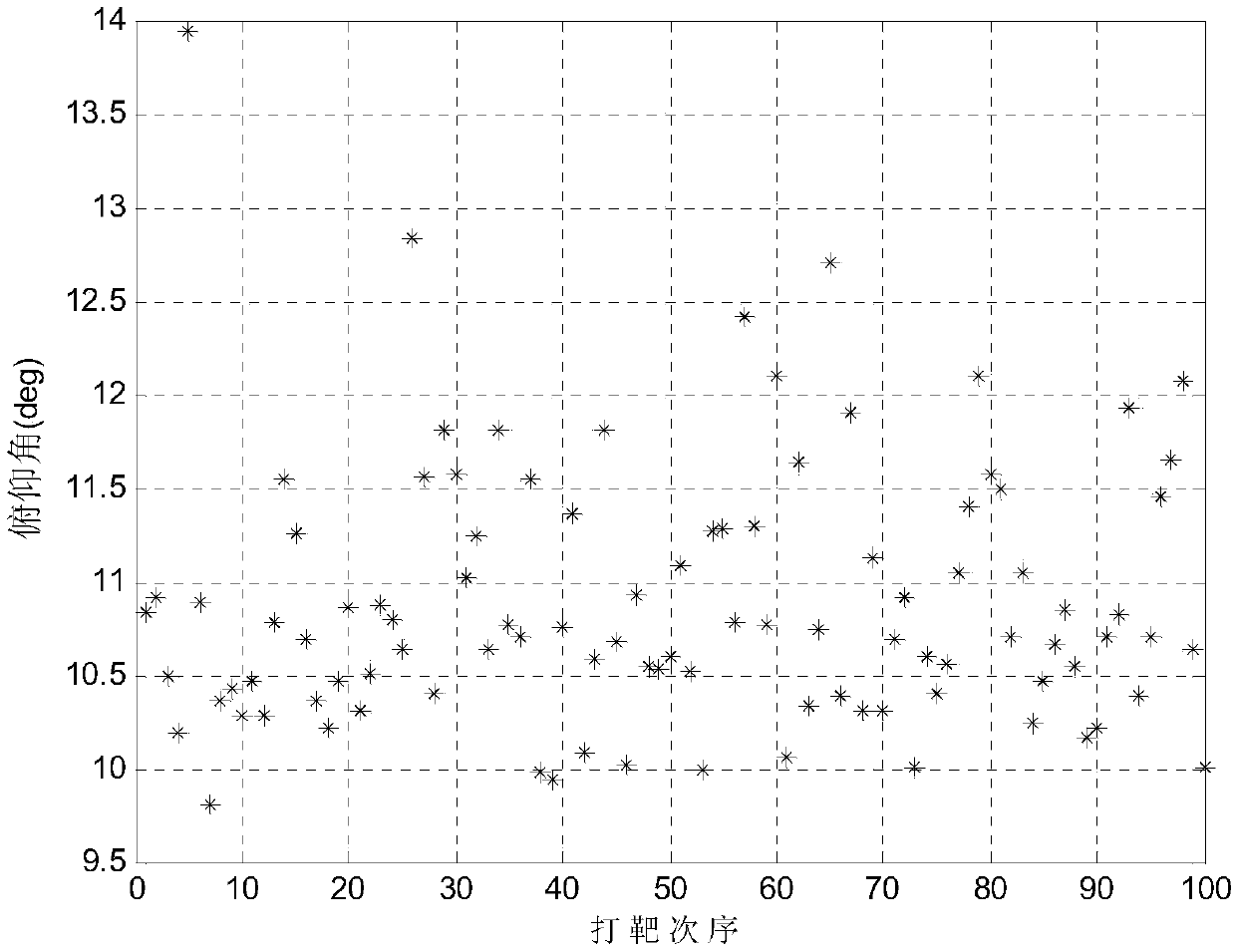
[0052] The effectiveness of the method of the present invention is illustrated below through simulation.

[0053] The trajectory of the RLV approach and landing segment is divided into steep glide segment, arc segment, exponential transition segment and shallow glide segment. The specific off-line trajectory design method can be found in the literature (G.H.Barton and S.G.Tragesser, Autolanding trajectorydesign for the X-34, AIAA -99-4161,1999.), this simulation example only gives the relevant parameters of the designed trajectory.

[0054] The coordinate system is established with the projection of the starting point of approach and landing on the ground as the origin, the x-axis points to the touchdown point, the y-axis is perpendicular to the x-axis and points to the sky, and the z-axis is determined according to the right-hand rule. The position of the aircraft in the coordinate system is defined by (x, h, s) said. Let the coordinates of the starting point of the approach...


PUM


Abstract

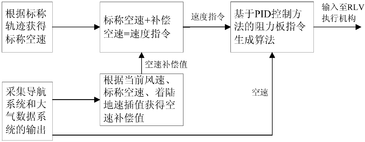
The invention relates to an RLV auto-landing segment speed control method based on a nominal speed compensation idea. The method comprises steps that firstly, nominal locus of an RLV auto-landing segment is designed, and a corresponding nominal air speed is acquired; secondly, a navigation ground speed and an air speed outputted by an atmosphere data system are utilized to determine a wind speed and the direction, a speed compensation item is determined through utilizing an interpolation method according to technical indexes such as the nominal air speed, a landing field wind field and ground contact ground speed requirements, and the speed compensation item is superposed into a nominal air speed generation speed instruction; and lastly, a flap control system is utilized to generate a flap drift angle to realize speed instruction tracking. The method is advantaged in that influence of tail wind and countrary wind on landing precision and attitude in an RLV landing process can be effectively solved, and guidance precision is improved.

Description

technical field [0001] The invention relates to a speed control method of an RLV approach and landing section based on the idea of ​​nominal speed compensation, which can be used for the design of the speed control law of the RLV approach and landing section. Background technique [0002] Reusable launch vehicles (RLV) are space shuttle vehicles that combine the features and functions of spacecraft and aircraft. They can stay in orbit to complete various space tasks, and can also return safely and accurately like an airplane. ground. Due to its reusable characteristics, RLV will become a highly reliable carrier for human beings to explore the universe at a low cost and a military weapon for competing for space supremacy. Therefore, the major powers in the world continue to invest huge resources in its research and development, and conduct new research and exploration. [0003] The return and reentry process of RLV must meet the constraints of dynamic pressure, heat flow an...

Claims


Application Information

Patent Timeline
Patent Type & Authority Patents(China)
IPC IPC(8): G05D1/06
CPCG05D1/0676
Inventor 严晗何英姿
Owner BEIJING INST OF CONTROL ENG
Why Eureka
Try Eureka