Data recording method, user equipment, and storage equipment
A technology for user equipment and storage equipment, applied in the electronic field, can solve the problems of increasing the cost of entry, and achieve the effect of reducing the cost of entry
- Summary
- Abstract
- Description
- Claims
- Application Information
AI Technical Summary
Problems solved by technology
Method used
Image

Examples
Embodiment 1
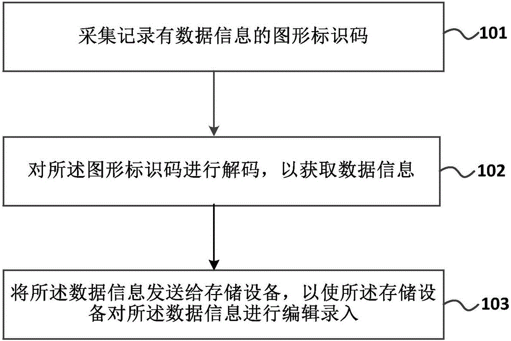
[0077] figure 1 A schematic flow chart of a data entry method provided in Embodiment 1 of the present invention, as shown in figure 1 As shown, a data entry method provided by Embodiment 1 of the present invention is applied to a user device, and may specifically include the following steps:
[0078] 101. Collect and record the graphic identification code with data information.
[0079] Specifically, graphic identification codes include but are not limited to QR codes and barcodes. User equipment includes but is not limited to mobile phones, tablet computers, etc. that can collect graphic identification codes and are used for the daily needs of users. The function of collecting the graphic identification code is used to collect the graphic identification code, wherein collecting the graphic identification code is one of many functions of the user equipment.
[0080] 102. Decode the graphic identification code to obtain data information.
[0081] Specifically, after the grap...
Embodiment 2
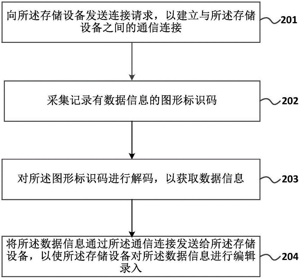
[0087] figure 2 A schematic flow chart of a data entry method provided by Embodiment 2 of the present invention, such as figure 2 As shown, a data entry method provided by Embodiment 2 of the present invention is applied to a user device, and may specifically include the following steps:
[0088] 201 Send a connection request to the storage device, so as to establish a communication connection with the storage device.
[0089] Specifically, in order to ensure the battery life of the user equipment, when it is necessary to collect and decode the graphic identification code, a communication connection is established with the storage device. The communication connection of the device, wherein, the sending of the connection request includes automatic sending and manual sending, wherein the automatic sending includes automatically connecting with the storage device when the user device collects the graphic identification code, or connecting with the storage device when the user ...
Embodiment 3
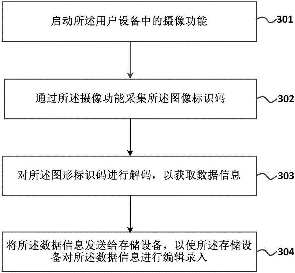
[0103] image 3 A schematic flow diagram of a data entry method provided by Embodiment 3 of the present invention, as shown in image 3 As shown, a data entry method provided by Embodiment 3 of the present invention is applied to a user device, and may specifically include the following steps:
[0104] 301. Start a camera function in the user equipment.
[0105] Specifically, the user equipment carries a camera function. Taking a mobile phone as an example, the camera function in the mobile phone is activated to collect the graphic identification code through the camera function.
[0106] 302. Collect the image identification code by using the camera function.
[0107] Specifically, the user equipment collects the graphic identification code through the camera function of the user equipment, and collects the graphic identification code by scanning the graphic identification code after starting the camera function. function can realize the collection of graphic identificatio...
PUM
 Abstract
Description
Claims
Application Information