
Electromagnetic magnet with manual control and state detecting functions

A state detection and electromagnet technology, applied in the direction of electromagnets, electromagnets, circuits, etc. with armatures, can solve problems such as the inability of the electromagnet to work, the inability to judge whether the electromagnet is working, the surge in the temperature rise of the coil, etc.

Pending Publication Date: 2017-02-22
陕西众力通用电器股份有限公司
View PDF0 Cites 4 Cited by
  • Summary
  • Abstract
  • Description
  • Claims
  • Application Information

AI Technical Summary

Problems solved by technology

[0002] Existing electromagnets all work after inputting the operating voltage, which will cause limitations in the use of users: that is, when the input power of the electromagnet fails and cannot provide power to the electromagnet, the electromagnet will not work
And the current electromagnet does not have the function of state detection. Without state detection, it is impossible to judge whether the electromagnet is working. damage

Method used


Image

  • Electromagnetic magnet with manual control and state detecting functions
  • Electromagnetic magnet with manual control and state detecting functions
  • Electromagnetic magnet with manual control and state detecting functions

Examples


Embodiment Construction

[0014] combined with figure 1 , 2 , 3, 4 describe an embodiment of the present invention.

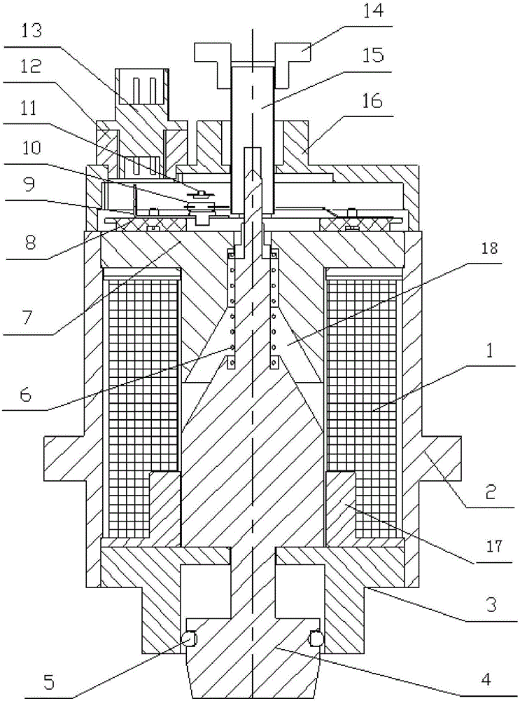
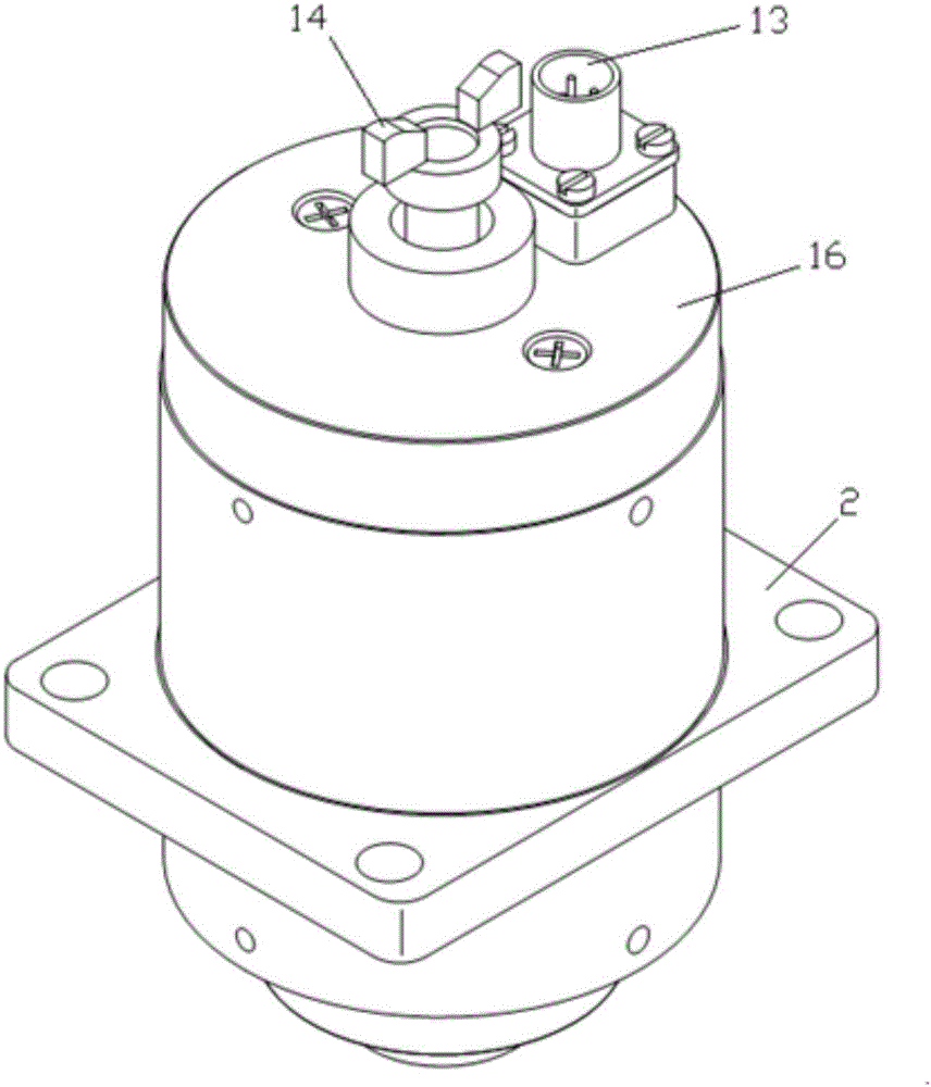
[0015] A double-coil electromagnet with manual control and state detection has a casing 2, a coil frame 17 is installed in the casing 2, a coil 1 is wound on the coil frame 17, and the upper end of the casing 2 is equipped with a "T " type iron core 7, the lower end is equipped with "T" type cover plate 3; There is a through hole 18 whose lower end is a tapered mouth; the base 8 is riveted with a static reed 9, a moving reed 10 and a state detection reed 11, and the static reed 9 and the moving reed 10 are normally closed contacts. The moving reed 10 and the state detection reed 11 are normally open contacts, and the base 8 is equipped with an inverted "T"-shaped dust cover 16; the coil frame 17 is inserted with an armature 4, and the upper part of the armature 4 It is in the shape of a tapered rod, the taper is adapted to the taper mouth, the rod is inserted into the through hole 18...


PUM


Abstract

Disclosed is an electromagnetic magnet with manual control and state detecting functions. A coil frame is mounted in a cover shell; the coil frame is wound by a coil; a "T"-shaped iron core is assembled at the upper end of the cover shell while a "T"-shaped cover plate is assembled at the lower end of the cover shell; the lower end of the "T"-shaped iron core extends into the coil frame; a base is fixed at the top end; a through hole with a conical opening in the lower end is formed in the center of the "T"-shaped iron core; a static spring sheet, a movable spring sheet and a state detection spring sheet are riveted on the base; an inverted "T"-shaped dustproof cover is assembled on the base; an armature is inserted in the coil frame; the upper part of the armature adopts a conical rod shape, and the conical shape part is adapted with the conical opening while the rod-shaped part is inserted in the through hole and passes through the base to extend to the upward side of the base; a reset spring is assembled on the rod-shaped lower part while a threaded rod is fixed on the upper part; the threaded rod is equipped with a butterfly nut; the lower end of the armature is adapted in a slot hole of the cover plate; a socket is mounted on the inverted "T"-shaped dustproof cover; and the socket is electrically connected with the state detection spring sheet and the coil separately. The electromagnetic magnet has the state detection function and reliability in long-term electrified operation; and meanwhile, the electromagnetic magnet can be manually controlled in power outage to realize function switching.

Description

technical field [0001] The invention belongs to the technical field of electromagnet manufacturing, and in particular relates to an electromagnet with manual control and state detection. Background technique [0002] Existing electromagnets all work after inputting the operating voltage, which will cause limitations in the use of users: that is, the electromagnet cannot work when the input power of the electromagnet fails and cannot provide power to the electromagnet. And the current electromagnet does not have the function of state detection. Without state detection, it is impossible to judge whether the electromagnet is working. damage. Contents of the invention [0003] The technical problem solved by the present invention is to design an electromagnet with manual control and state detection, which not only has the state detection function, but also has long-term power-on work reliability, and can be manually controlled to make the electromagnet move in place when the ...

Claims


Application Information

Patent Timeline
IPC IPC(8): H01F7/16H01F7/08
CPCH01F7/081H01F7/1615H01F2007/086
Inventor 雷建伟王建国陈汉宁张彦杰
Owner 陕西众力通用电器股份有限公司
Learn More