
A delay controllable power supply mechanism and method

A technology of power supply mechanism and delay circuit, which is applied to offensive equipment, fuzes, weapon accessories, etc., can solve problems such as poor safety and false triggering, and achieve the effect of high safety.

Active Publication Date: 2022-08-05
湖北三江航天红林探控有限公司
View PDF8 Cites 0 Cited by
  • Summary
  • Abstract
  • Description
  • Claims
  • Application Information

AI Technical Summary

Problems solved by technology

[0003] For a destructive weapon system, whether it is directly powered by an external power supply or a built-in power supply, there is a risk of false triggering, and the security is poor. Prevent the launch process from the source, so that the security of the system will be fundamentally guaranteed

Method used


Image

  • A delay controllable power supply mechanism and method
  • A delay controllable power supply mechanism and method
  • A delay controllable power supply mechanism and method

Examples


Embodiment Construction

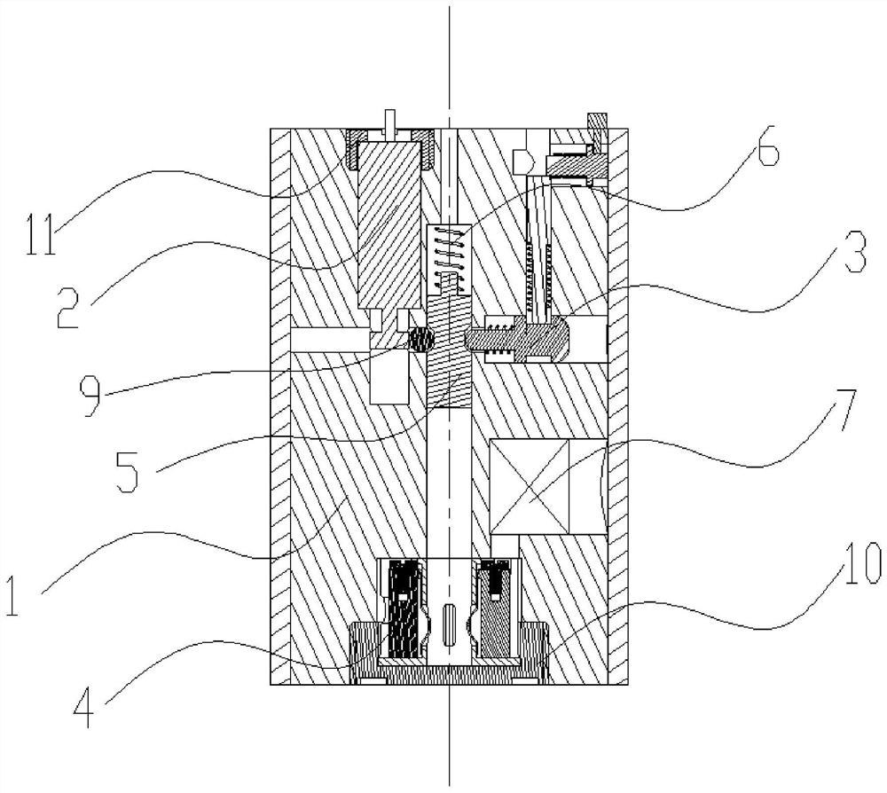
[0041] In order to make the objectives, technical solutions and advantages of the present invention clearer, the present invention will be further described in detail below with reference to the accompanying drawings and embodiments. It should be understood that the specific embodiments described herein are only used to explain the present invention, but not to limit the present invention. In addition, the technical features involved in the various embodiments of the present invention described below can be combined with each other as long as they do not conflict with each other. The present invention will be further described in detail below in conjunction with specific embodiments.

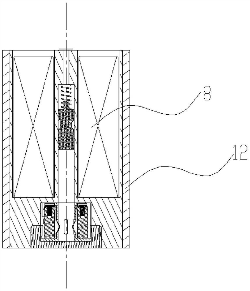
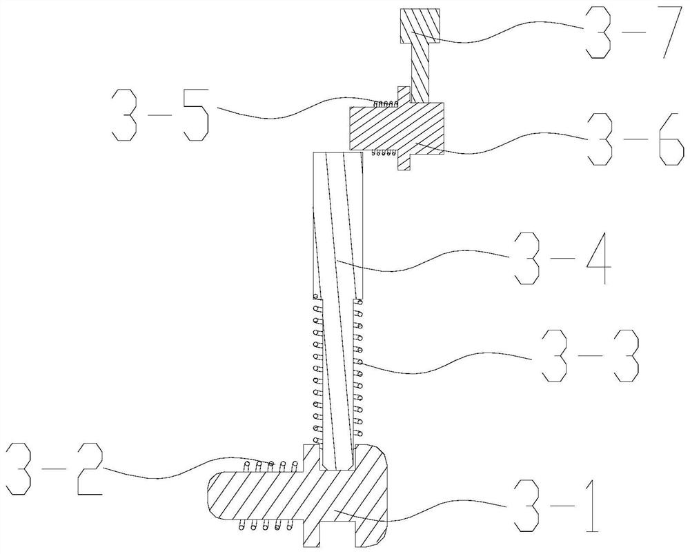
[0042] As a preferred embodiment of the present invention, as Figure 1-6 As shown, the present invention provides a delay controllable power supply mechanism, including the following detailed structure.

[0043] The main body 1 is used to install and fix various components and form a whole me...


PUM


Abstract

The invention discloses a time delay controllable power supply mechanism, which mainly includes a main body, a conductor, a transfer switch, a time delay circuit module, a battery, etc.; the electric pin puller and the smoothbore pin are two fuses, and the electric pin puller and The smoothbore pin part locks the conductor to prevent it from malfunctioning. At this time, the transfer switch is in an off state, and the battery cannot supply power to the delay circuit at this time. When launching, external power is supplied to the electric pin puller first, and the electric pin puller acts to release the first restraint on the conductor; then the delay controllable power supply mechanism is pushed out by the propellant in the launching device, and the smoothbore pin part is in the discharge tube. After the wall, the cylinder wall constraint of the launching device is lost, and the second constraint on the conductor is released. Under the action of the driving spring, the conductor is pushed into the transfer switch, the transfer switch is switched from off to on state, the battery supplies power to the delay circuit module, when the delay time arrives, the delay circuit outputs electrical energy. After the invention is separated from the transmitting device, the electric energy is generated after a delay, and the safety is high.

Description

technical field [0001] The invention belongs to the technical field of power supply systems for transmitting devices, and in particular relates to a delay-controllable power supply mechanism and method. Background technique [0002] The current power supply system of the weapon launching device adopts the structure of an external power supply, which can supply power to the system before launching, but the external power supply is cut off after launching, and the launching device cannot be powered during flight. Even if some devices to be launched have a built-in power supply, they are generally powered directly. [0003] For a devastating weapon system, whether it is directly powered by an external power supply or powered by a built-in power supply, there is a risk of false triggering, and the safety is poor. The source is prevented from acting during the launch process, so that the security of the system will be fundamentally guaranteed. SUMMARY OF THE INVENTION [0004...

Claims


Application Information

Patent Timeline
Patent Type & Authority Patents(China)
IPC IPC(8): F42C15/20F42C15/40
CPCF42C15/20F42C15/40
Inventor 李响周莹
Owner 湖北三江航天红林探控有限公司
Learn More