
Detection circuit, detection method and chip

A detection circuit and circuit technology, applied in the network field, can solve problems such as increasing the circuit scale, and achieve the effect of reducing the scale of the detection circuit

Active Publication Date: 2022-07-29
BEIJING TASSON SCI & TECH CO LTD
View PDF5 Cites 0 Cited by
  • Summary
  • Abstract
  • Description
  • Claims
  • Application Information

AI Technical Summary

Problems solved by technology

However, using the traditional way to detect the interface state will increase the scale of the circuit

Method used


Image

  • Detection circuit, detection method and chip
  • Detection circuit, detection method and chip
  • Detection circuit, detection method and chip

Examples


Embodiment Construction

[0050] In order to make the objectives, technical solutions and advantages of the present application more clear, the present application will be further described in detail below with reference to the accompanying drawings and embodiments. It should be understood that the specific embodiments described herein are only used to explain the present application, but not to limit the present application.

[0051] The detection circuit provided by the present application can be applied to a chip, a field programmable gate array chip, or other hardware circuit devices to perform status detection of an Ethernet port. This embodiment takes the vehicle Ethernet port as an example to describe the detection circuit and the detection method. Therefore, in this embodiment, the above chip may be a vehicle Ethernet chip.

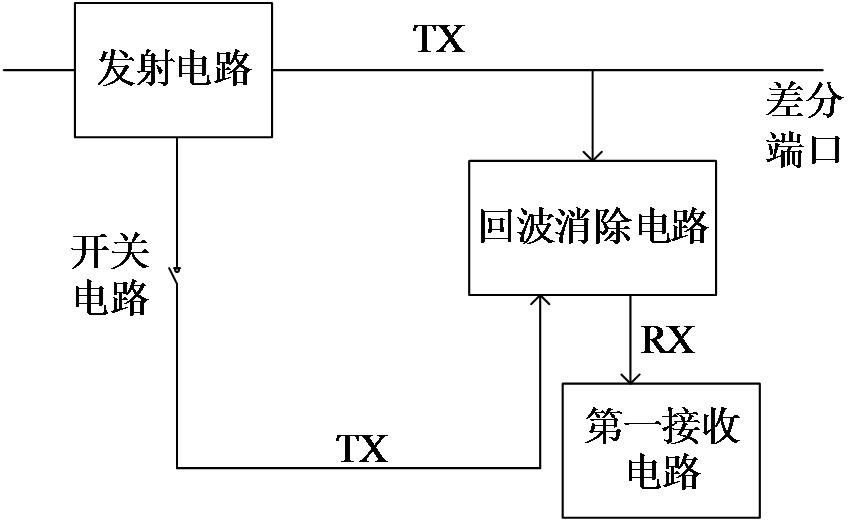
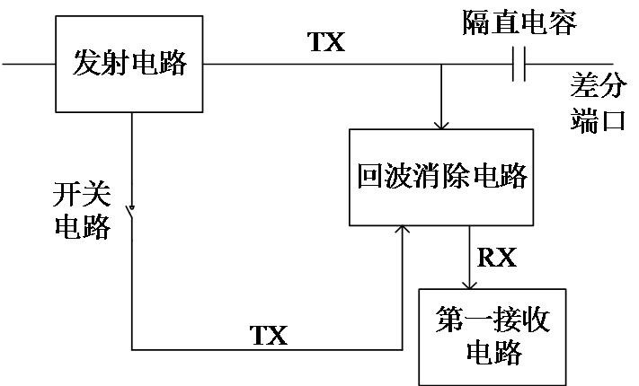
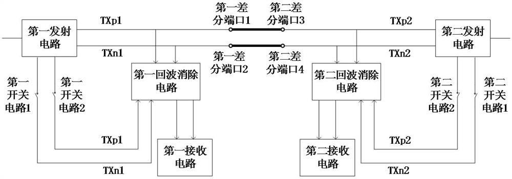
[0052] figure 1 A schematic structural diagram of a detection circuit provided for an embodiment, the detection circuit includes: two transceiver circuits, and differenti...


PUM


Abstract

The present application relates to a detection circuit, a detection method and a chip. The detection circuit includes: two transceiver circuits, the differential ports between the two transceiver circuits are connected to each other, the transceiver circuit includes a transmitter circuit, an echo cancellation circuit, a switch circuit and a receiver circuit, and the first output end of the transmitter circuit is connected to the echo cancellation circuit. The first input end of the circuit forms a first path, the second output end of the transmitting circuit, the switch circuit and the second input end of the echo cancellation circuit form a second path, wherein the receiving circuit is used to conduct the second path in the switch circuit When , determine whether the differential port is abnormal according to the output signal of the echo cancellation circuit. The detection circuit can avoid adding additional analog circuits to realize differential port status detection, and can determine whether the differential port is abnormal only by controlling the working status of the echo cancellation circuit by the switch circuit, so that on the basis of ensuring the differential port status detection function, it can Reduce the size of the detection circuit.

Description

technical field [0001] The present application relates to the field of network technology, and in particular, to a detection circuit, a detection method and a chip. Background technique [0002] As there are more and more electronic devices in the car, the challenge to bandwidth is also getting higher and higher. The use of in-vehicle Ethernet technology can satisfy the calculation and communication of different devices in the car. In order to keep the calculation and communication process smooth, it is necessary to detect the interface status of the in-vehicle Ethernet in real time, so as to solve the problem of interface connection failure in time according to the detection results, so that the interface of the in-vehicle Ethernet can maintain a normal connection state. [0003] In the traditional technology, an analog detection circuit is added to the Ethernet physical layer interface circuit to perform real-time detection on the interface state of the vehicle Ethernet. ...

Claims


Application Information

Patent Timeline
Patent Type & Authority Patents(China)
IPC IPC(8): H04B3/46
Inventor 房亮魏江龙应子罡曹正刘银栋张雄波于万斌
Owner BEIJING TASSON SCI & TECH CO LTD
Learn More