

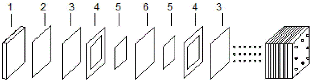
Redox flow cell stack
A technology of liquid flow batteries and electric stacks, which is applied to battery electrodes, fuel cells, circuits, etc., can solve the problems of battery system overall efficiency decline, electrode overvoltage, and electric stack scrapping, etc., and achieve faster hydrogen ion transmission and faster response Speed up and improve the effect of stability
- Summary
- Abstract
- Description
- Claims
- Application Information
AI Technical Summary
Problems solved by technology
Method used
Image

Examples
Embodiment 1
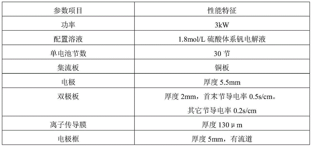
[0029] Example 1 The first and last cells use bipolar plates with higher conductivity
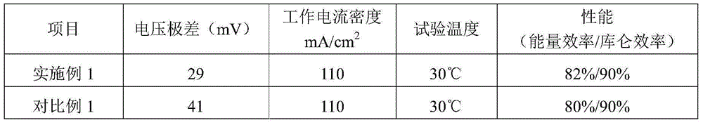
[0030] Voltage range test method: Connect the assembled cell stack with the electrolyte circulation system and the battery management system, charge and discharge it at a fixed current density, and record the last charge after multiple charge and discharge cycles. The voltage of the discharge cycle is extremely poor. The specific method is to record the actual voltage value of each single battery when the battery is charged to a certain voltage value during the charging process (for example: the all-vanadium redox flow battery is 1.50V average voltage multiplied by the number of single cells), and all The voltage difference between the two single cells with the maximum voltage and the minimum voltage in the single cell is the voltage range of the stack at the corresponding current density.
[0031] Table 1
[0032]
[0033] The specific parameters of the electric stack of embodiment 1 ...
Embodiment 2
[0039] Example 2 The bipolar plates of the first and last single cells are treated by electrochemical deposition
[0040] table 3
[0041] Part Name performance characteristics power 20kW configuration solution 1.0mol / L sulfuric acid / hydrochloric acid mixed acid system vanadium electrolyte Number of cells 46 knots Collector plate copper plate electrode Thickness 5.5mm bipolar plate The thickness is 1.5mm, and the first and last sections are treated with electrochemical deposition ion conducting membrane Thickness 150μm, surface resistance 0.5Ω / cm 2 .
[0042] The specific parameters of the stack in Example 2 are shown in Table 7. A 46-cell stack is used. The single cells of the stack are connected in series, the thickness of the ion-conducting membrane is 150 μm, and the measured value of the surface resistance is 0.5 Ω / cm 2 . The first and last bipolar plates are treated with chemical deposition catalyst, and the ...
Embodiment 3
[0051] Example 3 The first and last cells use bipolar plates with relatively high roughness
[0052] Table 6
[0053]
[0054] The specific parameters of the battery stack in Example 3 are shown in Table 6. The assembled 1kW battery stack is connected to the electrolyte circulation system and the battery management system, and the battery is charged at 150mA / cm 2 Charge and discharge at the current density. When the battery runs stably for 19 charge-discharge cycles, record the voltage extreme difference at the end of the 20th charge-discharge cycle.
PUM
| Property | Measurement | Unit |
|---|---|---|
| thickness | aaaaa | aaaaa |
| thickness | aaaaa | aaaaa |
| surface resistance | aaaaa | aaaaa |
Abstract
Description
Claims
Application Information