

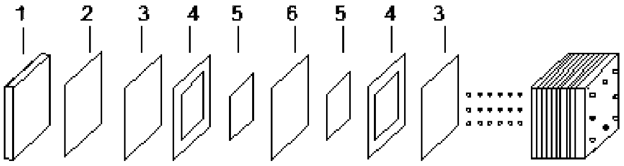
Flow battery stack structure
A technology of liquid flow batteries and electric stacks, which is applied in the direction of fuel cells, circuits, electrical components, etc., can solve the problems of the overall efficiency of the battery system, electrode overvoltage, scrapping of electric stacks, etc., so as to reduce the assembly and production costs of electric stacks, Effects of improving voltage efficiency and improving conductivity
- Summary
- Abstract
- Description
- Claims
- Application Information
AI Technical Summary
Problems solved by technology
Method used
Image

Examples
Embodiment 1
[0026] Example 1 The electrodes of the first and last cells are different from the electrodes of other cells
Embodiment 11
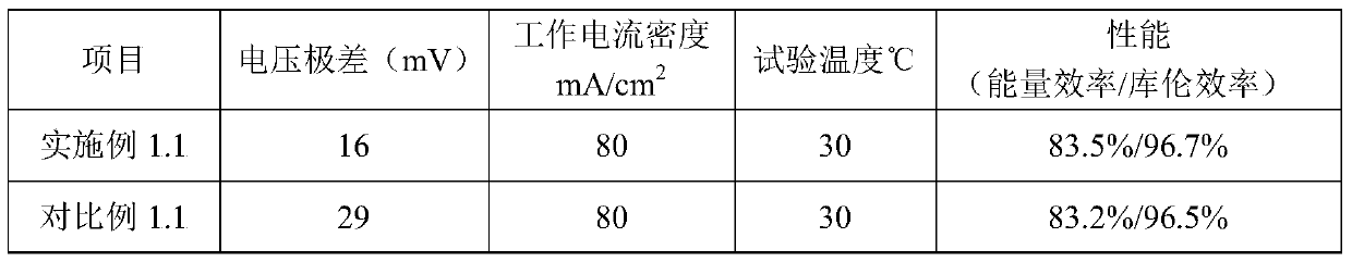
[0027] Example 1.1 Thinning the Electrode Thickness of the First and Last Cells
[0028] Voltage range test method: Connect the assembled cell stack with the electrolyte circulation system and the battery management system, charge and discharge it at a fixed current density, and record the last charge after multiple charge and discharge cycles. The voltage of the discharge cycle is extremely poor. The specific method is to record the actual voltage value of each single battery when the battery is charged to a certain voltage value during the charging process (for example: the all-vanadium redox flow battery is 1.50V average voltage multiplied by the number of single cells), and all The voltage difference between the two single cells with the maximum voltage and the minimum voltage in the single cell is the voltage range of the stack at the corresponding current density.
[0029] Table 1
[0030] parameter item performance characteristics power 2kW con...
Embodiment 12
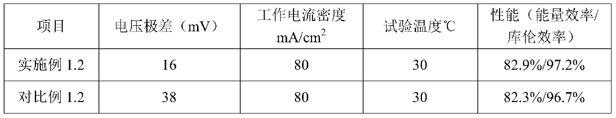
[0037] Example 1.2 Thicken the electrode thickness of the first and last cells
[0038] Example 1.2 The specific parameters of the stack structure of the liquid flow battery are shown in Table 3:
[0039] table 3
[0040] parameter item performance characteristics power 10kW
[0041] configuration solution 2mol / L sulfuric acid / hydrochloric acid mixed acid system vanadium electrolyte Solution volume 800L(15kWh) Number of cells 40 knots Collector plate copper plate electrode The thickness of the first and last section is 7.5mm, and the thickness of other sections is 6.5mm; bipolar plate Thickness 2mm ion conducting membrane Thickness 120um Electrode frame Thickness 4.5mm
[0042] Connect the assembled 10kW stack to the electrolyte circulation system and the battery management system, and use 80mA / cm 2 The current density of the battery is charged and discharged. When the battery runs stably f...
PUM
| Property | Measurement | Unit |
|---|---|---|
| thickness | aaaaa | aaaaa |
| thickness | aaaaa | aaaaa |
Abstract
Description
Claims
Application Information