Adaptive Calibration Method of Microphone Array Output Signal Based on rls Algorithm
What is AI technical title?
AI technical title is built by Patsnap AI team. It summarizes the technical point description of the patent document.
A microphone array and output signal technology, which is applied in the field of signal processing, can solve the problems of output signal attenuation or distortion, and achieve the effect of improving the accuracy of calibration
Active Publication Date: 2019-01-22
SYSU CMU SHUNDE INT JOINT RES INST +1
View PDF5 Cites 0 Cited by
Summary
Abstract
Description
Claims
Application Information
AI Technical Summary
This helps you quickly interpret patents by identifying the three key elements:
Problems solved by technology
Method used
Benefits of technology
Problems solved by technology
[0006] The purpose of the present invention is to realize the adaptive calibration of the output signal of the microphone array, solve the problem that the beamformer causes serious attenuation or distortion of the output signal due to the mismatch of the microphone, so that the output signal can achieve faster error convergence speed and less distortion error
Method used
Image
Click on the blue label to locate the original text in one second.
Reading with bidirectional positioning of images and text.
Examples
Embodiment 1
[0042] Such as Figure 4 Said, the calibration method provided by the present invention comprises the following steps:
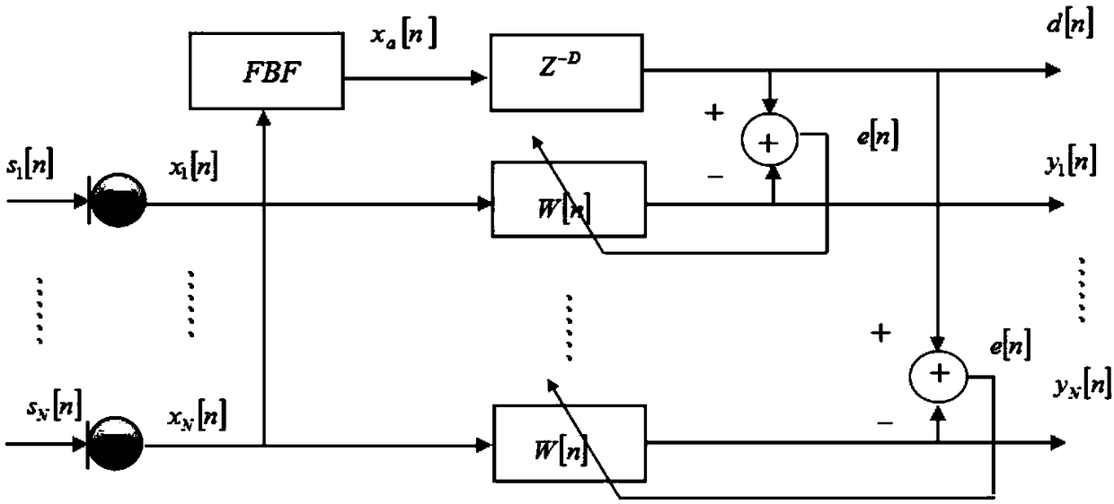
[0043] S1. Select the output signal x of the nth group of microphone array N microphones 0 (n), x 1 (n), x 2 (n),...,x N-1 (n) as a signal to be calibrated;
[0044] S2. Select the nth group output signal x of one of the microphones i (n) Input to the fixed beamformer, the fixed beamformer outputs the signal x i The characteristics of (n) are averaged to obtain the output signal x a (n);
[0045] S3. Pass the delay filter to x a (n) Obtain the reference signal d(n) after performing time delay compensation;
[0046] S4. Output signal x 0 (n), x 1 (n), x 2 (n),...,x N-1 (n) respectively input to the calibration filter W 0 [n], calibration filter W 1 [n], ..., calibration filter W N-1 [n] for calibration, calibration filter W 0 [n], calibration filter W 1 [n], ..., calibration filter W N-1 [n] Output the calibrated output signal y respectivel...
Embodiment 2
[0061] In this embodiment, specific experiments are carried out on the basis of the method provided in Embodiment 1. The flow chart of the experiment is as Figure 5 As shown, the experiment of this embodiment takes N=8 microphones to form a microphone array according to a certain topology, such as figure 1 As shown, after the voice signal s(n) from the sound source is received by the microphone, the microphone outputs the signal x N (n). In the experiment, the output signals of 8 microphones are input into the fixed beamformer, and the fixed beamformer averages the output signal characteristics of each microphone to obtain the signal x a (n). x a (n) is used as a reliable and ideal reference signal d(n) after time delay compensation. Afterwards, each microphone output signal x N (n) are respectively input into the same calibration filter, and its output signal y N (n) as the calibrated output signal. After the calibration is completed, the coefficients of the calibrat...
PUM
Abstract
The invention relates to a microphone array output signal adaptive calibration method bases on an RLS algorithm, which solves a problem that a beam former severely attenuate or distort output signals due to microphone mismatching, and enables the output signals to achieve faster error convergence rate and fewer distortion errors. At the same time, the calibration method provided by the invention processes the output signals by group. Calibration of the current group of output signals is based on a calibration filter updated by data of a former group of output signals, as the updated calibration filter can well fit features of the output signals, the calibration accuracy is improved compared with the prior art, and coefficients of the calibration filter are changed by adapting to features of the output signals in the whole calibration process, so that the calibration method provided by the invention can well adapt to large change in output features of a microphone array due to factors such as aging or environmental change of the microphone array, thereby effectively calibrating the output signals.
Description
technical field [0001] The present invention relates to the technical field of signal processing, and more particularly, relates to an RLS algorithm-based adaptive calibration method for microphone array output signals. Background technique [0002] Voice communication has become one of the most important means of human information exchange, and a series of methods and theories that use microphone arrays to process voice signals have been studied for more than 20 years. When a single microphone is used to receive a voice signal, what the single microphone receives is a mixed signal composed of multiple sound sources and environmental noise. At the same time, due to factors such as the mobility of the sound source and the multipath reflection and reverberation of various other sounds in the room, the signal quality output by a single microphone will degrade, resulting in a serious deterioration in the quality of voice communication. Aiming at the shortcomings of a single mic...
Claims
Application Information
Patent Timeline
Application Date:The date an application was filed.
Publication Date:The date a patent or application was officially published.
First Publication Date:The earliest publication date of a patent with the same application number.
Issue Date:Publication date of the patent grant document.
PCT Entry Date:The Entry date of PCT National Phase.
Estimated Expiry Date:The statutory expiry date of a patent right according to the Patent Law, and it is the longest term of protection that the patent right can achieve without the termination of the patent right due to other reasons(Term extension factor has been taken into account ).
Invalid Date:Actual expiry date is based on effective date or publication date of legal transaction data of invalid patent.

