
Hairdressing apparatus

A styling tool, technology for hair, applied in the direction of home appliance, hair comb, device for washing hair or scalp

Inactive Publication Date: 2017-02-22
WIK FAR EAST
View PDF5 Cites 0 Cited by
  • Summary
  • Abstract
  • Description
  • Claims
  • Application Information

AI Technical Summary

Problems solved by technology

However, these hair styling appliances have only one hair styling gap

Method used


Image

  • Hairdressing apparatus
  • Hairdressing apparatus
  • Hairdressing apparatus

Examples


Embodiment Construction

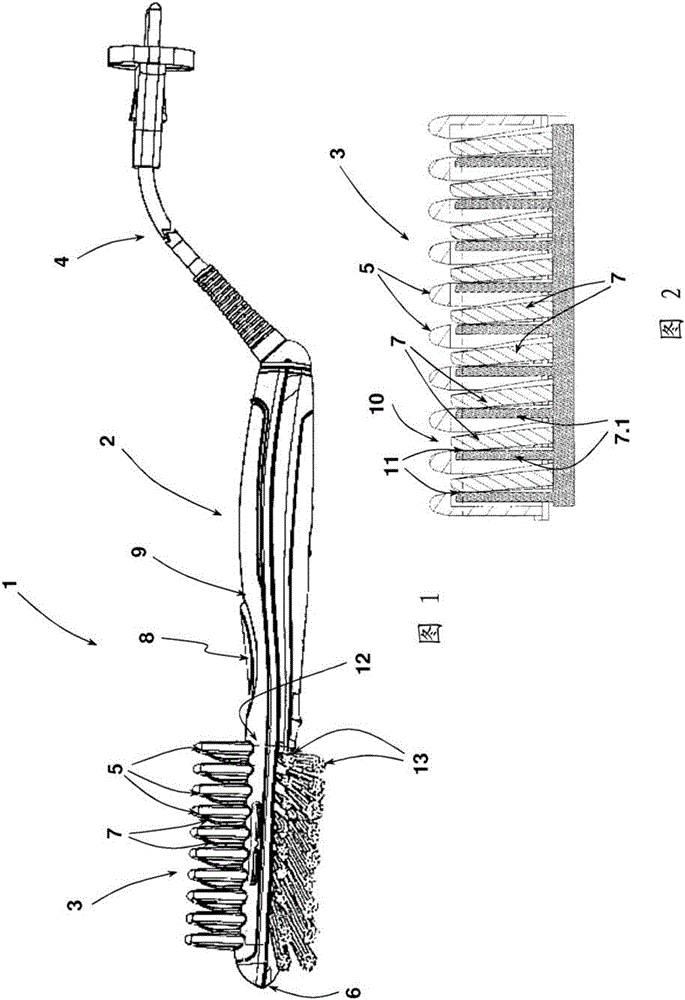
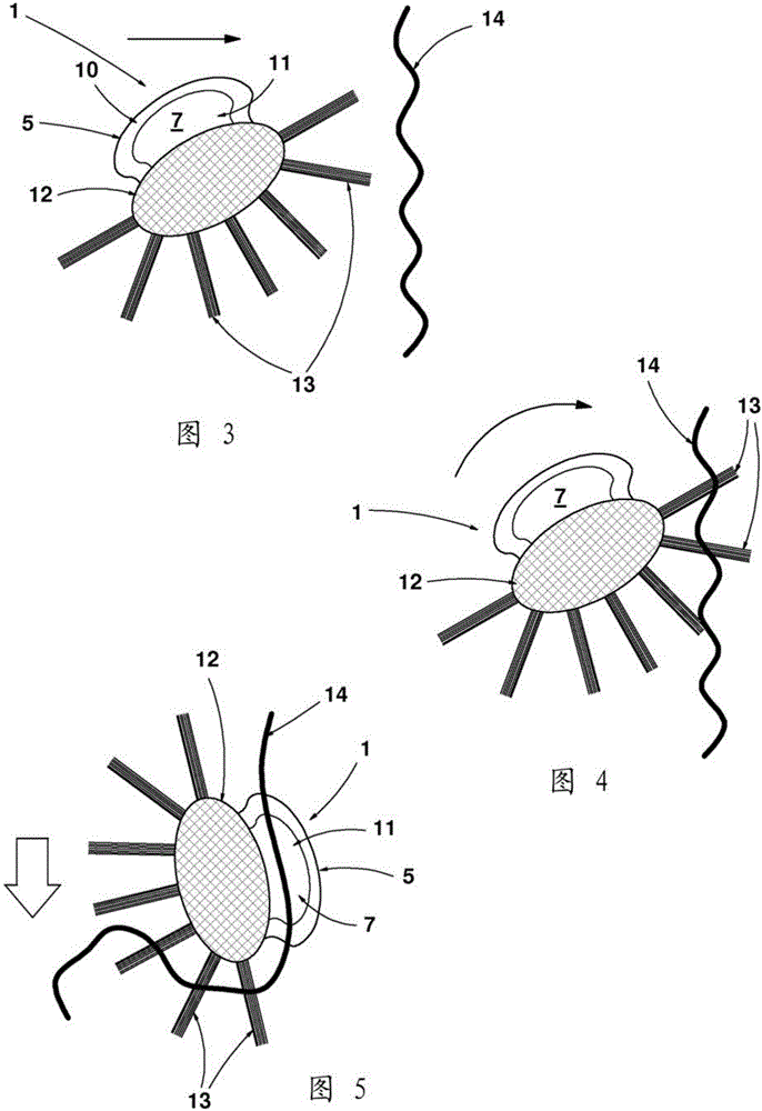
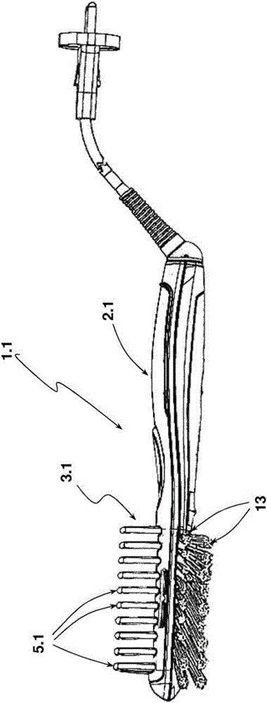
[0028] The hair styling appliance 1 has a styling tool 3 connected to a handle 2 . The styling tool 3 is electrically heated. For the power supply, the hair styling appliance 1 has an electrical connection cable 4 . The styling tool 3 is of comb-like design and features a row of fixed upright teeth 5 arranged at a distance from each other. In each tooth 5 , except for the outermost tooth in said row of teeth arranged adjacent to the tip 6 of the profiling tool 3 , a movable first profiling portion 7 is assigned to each tooth 5 . The styling parts 7 are collectively combined to form a styling part unit. The profiling unit is movable in the longitudinal direction of the tooth row and can be displaced in translation in the direction of the handle 2 from its position shown in FIG. 1 by actuation of a control element, which The element is designed as a button 8 in the exemplary embodiment presented. The tooth 5 is realized as a molded plastic part jointly with a cover shell 9 w...


PUM


Abstract

Hairdressing apparatus 10 for shaping hair, comprising a plurality of hollow teeth 20 which are attached to a hollow grip 30, which grip 30 functions as an air distribution chamber for supplying air to the teeth 20 when air is supplied to the hollow grip 30. The hairdresser apparatus 10 is characterized by the teeth 20 having at least one outlet opening 40 at only one side and above the tips 25 of the teeth 20, and wherein the at least one outlet opening 40 is formed as a channel which has an inclination in a direction upwards from the tips 25 of the teeth 20, such that air will be pressed against hair and upwards from the scalp.

Description

technical field [0001] The present invention relates to a hair styling appliance comprising a shaft, the hair styling appliance having a comb-like styling tool extending over only part of the circumference of the shaft and having teeth, the teeth each spaced apart from each other by a hair receptacle, arranged in a row in the longitudinal direction of the shaft, protruding from the shaft and each forming or having a styling portion made of a material with good thermal conductivity, wherein the two hair styling gaps separated Each of the molding sections forms a molding section pair. [0002] Such hair styling appliances are mainly used to straighten hair and are therefore also referred to as hair straighteners. The styling implements of this type of hair styling appliance comprise a row of teeth spaced apart from each other, wherein a pair of adjacent teeth spaced apart from each other each form a hair receptacle. For the hair styling process, each hair receptacle or at leas...

Claims


Application Information

Patent Timeline
IPC IPC(8): A45D2/00
CPCA45D1/04A45D2/002A45D2/44A45D24/10A45D24/16A46B5/0008A46B7/044A46B9/023A46B15/003A46B2200/104
Inventor M.科克
Owner WIK FAR EAST
Learn More