Rotatable end of dose feedback mechanism

A dose and rotating tower technology, applied in the direction of medicine equipment, infusion sets, other medical equipment, etc., can solve the problems of plunger driving parts movement, complexity and error indication

Inactive Publication Date: 2017-02-22
ELI LILLY & CO
View PDF12 Cites 2 Cited by
  • Summary
  • Abstract
  • Description
  • Claims
  • Application Information

AI Technical Summary

Problems solved by technology

Still other prior art devices may be undesirably complex or provide a false indication if an injection is interrupted, or may actually produce movement of the plunger drive member when an end-of-dose indication is indicated.

Method used


Image

  • Rotatable end of dose feedback mechanism
  • Rotatable end of dose feedback mechanism
  • Rotatable end of dose feedback mechanism

Examples


Embodiment Construction

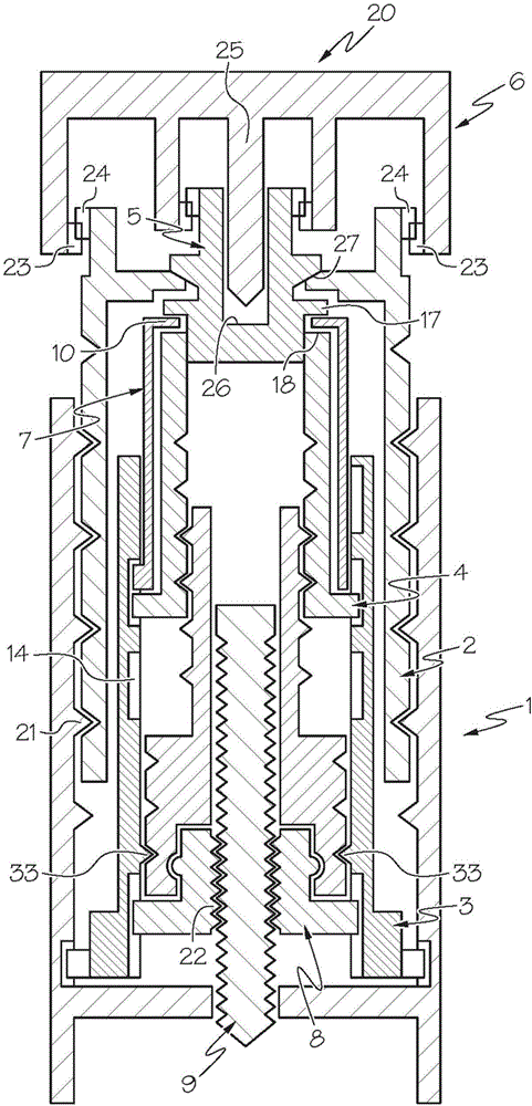
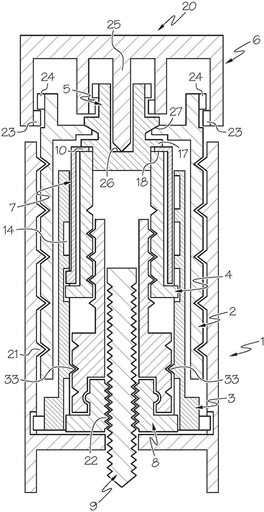
[0051] In the following, the term "main axis" defines a common axis for the mainly tubular part and for the entire injection device. First, although the description includes only the parts relevant to understanding the function of the signal characteristics of the end-of-dose notification mechanism, however, the accompanying picture Other parts may be shown that may be part of an injection device including this feature. figure 1- 4 and Figure 9- 12 The injection device disclosed is similar to the injection device disclosed in WO 2012 / 037938 A1 which is incorporated herein by reference, whereas Figure 6- The injection device of 8 is similar to the injection device disclosed in WO 2005 / 018721 which is hereby incorporated by reference.

[0052] The terms "upper", "lower", "upper", "lower", "upward" and "downward" refer to the attached picture rather than by reference to usage.

[0053] In all embodiments, the screw abuts a plunger in a drug-filled cartridge, and downward m...


PUM


Abstract

An injection device for injecting a medicament includes a housing, a dose setting member (20) movable to set a dose to be injected, and a signal part (7). The signal part rotates from a first rotational position to a second rotational position to increase loading on a spring or spring arm when a dose is set due to rotation of the dose setting member. An internal pressure builds up in the injection device during injection which results in the signal part being captured in the second rotational position between first and second internal parts of the injection device. After the internal pressure dissipates by a sufficient amount during injection, the signal part rotates under the urging of the loaded spring from the second rotational position back to the first rotational position. A portion of the signal part moves into contact with a surface when the signal part reaches the first rotational position to produce tactile or audible feedback indicating that an end of dose condition has been reached.

Description

[0001] Cross References to Related Applications [0002] This application claims priority under 35 U.S.C. §119(e) to U.S. Provisional Application No. 62 / 008,559, filed June 6, 2014 and incorporated herein by reference. technical field [0003] The present invention relates to an injection device, eg for manual or spring actuated injection, having an audible signal or a tactile signal or both to indicate when a dose is considered complete and when the injection may be terminated. Background technique [0004] Most injection devices on the market today that are capable of setting doses of various sizes visually count down to zero on the display device during injection. This allows the user to track the progress of the injection and determine when the mechanical components have reached their initial zero position. When the zero position has been reached, it is recommended that the user wait 5-6 seconds to allow the pressure that has built up in the device during injection to e...

Claims


Application Information

Patent Timeline
Patent Type & Authority Applications(China)
IPC IPC(8): A61M5/315A61M5/24A61M5/20
CPCA61M5/20A61M5/24A61M5/31551A61M5/3157A61M5/31585A61M2205/581A61M2205/582A61M5/31528
Inventor C·S·莫勒
Owner ELI LILLY & CO
Why Eureka
Try Eureka