

Assembly for securing an electronic unit and heat screen
A technology for electronic boxes and heat shields, which is applied to vehicle components, transportation and packaging, circuits or fluid pipelines, etc., and can solve problems such as tearing and damage
- Summary
- Abstract
- Description
- Claims
- Application Information
AI Technical Summary
Problems solved by technology
Method used
Image

Examples
Embodiment Construction
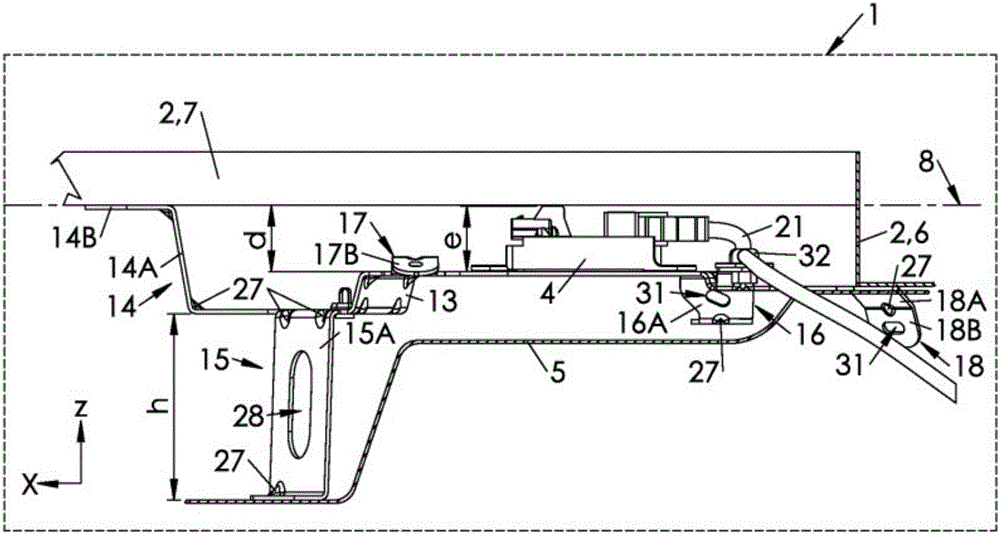
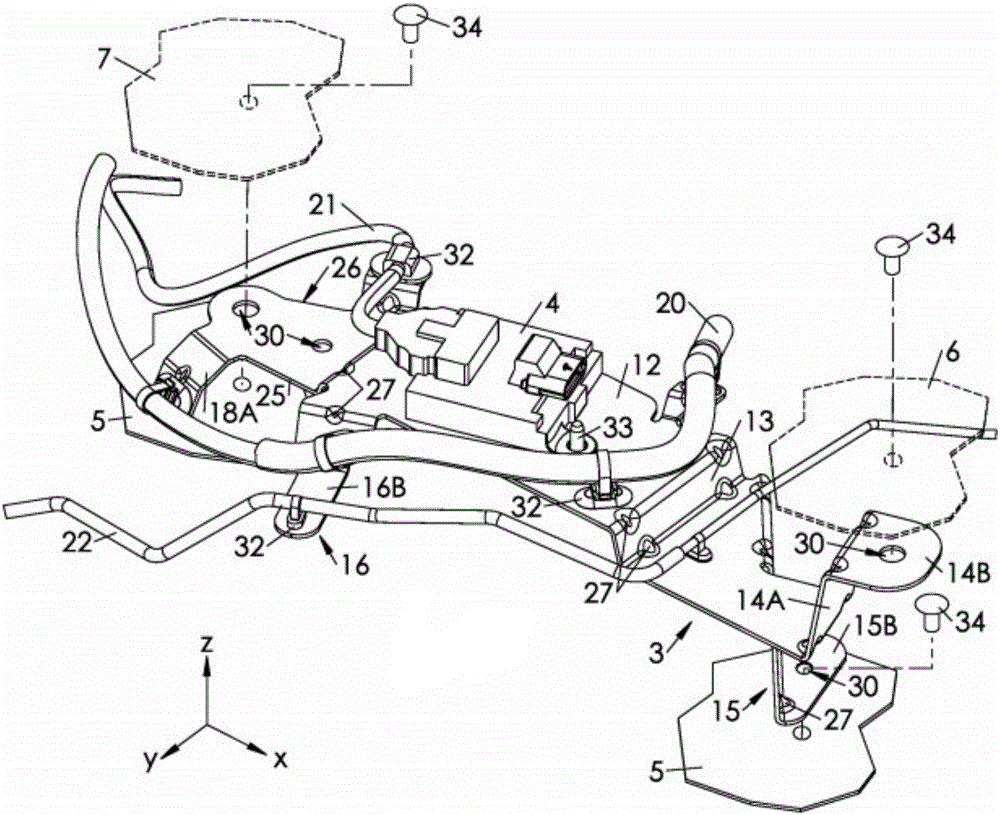
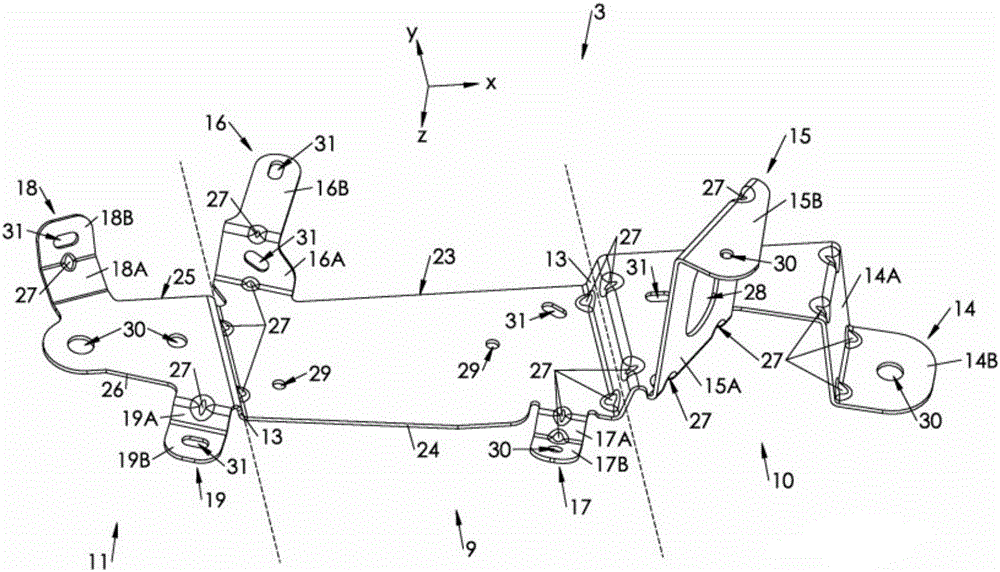
[0032] figure 1 A motor vehicle 1 is schematically shown comprising a compartment 2 on which a support 3 for securing an electronics box 4 and a heat shield 5 is fixed, mounted under the vehicle 1 .
[0033] More specifically, the wagon 2 comprises a longitudinal beam 6 extending substantially in the general direction of movement of the vehicle 1 , and a transverse beam 7 substantially perpendicular to the longitudinal beam 6 , forming a plane 8 of the wagon 2 .
[0034] An orthogonal coordinate system XYZ including two mutually perpendicular three axes is defined relative to the support 3, namely:
[0035] - the X axis, which defines the longitudinal, horizontal direction, coinciding with the usual direction of elongation of the support 3,
[0036] - the Y axis, which defines the horizontal, horizontal inverse, and the X axis, which defines the horizontal plane XY,
[0037] - the Z axis, which defines the vertical direction, perpendicular to the horizontal plane XY.
[003...
PUM
 Abstract
Description
Claims
Application Information